Heat pipe with flow guide part

A technology of a flow guide and a heat pipe, applied in the field of heat pipes, can solve the problems of affecting heat exchange efficiency, low heat exchange coefficient, uneven heat exchange, etc. Effect

Inactive Publication Date: 2017-06-27
ZHONGBEI UNIV
View PDF3 Cites 3 Cited by
  • Summary
  • Abstract
  • Description
  • Claims
  • Application Information

AI Technical Summary

Problems solved by technology

[0004] The current heat pipe, especially the multi-pipe loop heat pipe, in the design, the upper evaporation pipe is kept at the same height as the horizontal plane, such as figure 1 As shown, after the fluid is condensed, it cannot return to the middle of the evaporating end in time to participate in heat exchange, or only partially returns to the evaporating end, so that part of the condensed fluid still stays at both ends of the evaporating end, which greatly affects the efficiency of heat exchange and affects the heat exchange. Uniformity of
[0005] In view of the above problems, the present invention has been improved on the basis of the previous invention, and a new heat pipe is provided, thereby solving the problems of low heat transfer coefficient and uneven heat transfer in the case of heat pipe heat exchange

Method used


Image

  • Heat pipe with flow guide part
  • Heat pipe with flow guide part
  • Heat pipe with flow guide part

Examples


Embodiment Construction

[0037] The specific embodiments of the present invention will be described in detail below in conjunction with the accompanying drawings.

[0038] In this article, if there is no special explanation, when it comes to formulas, " / " means division, and "×" and "*" mean multiplication.

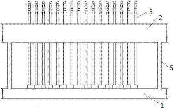
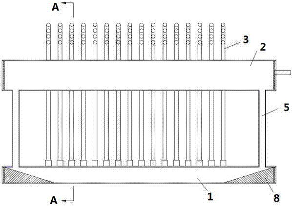
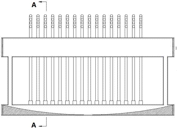
[0039] Such as figure 2 A heat pipe shown includes a lower header 1, an upper header 2, a connecting pipe 3 and a return pipe 5, the connecting pipe 2 communicates with the lower header 1 and the upper header 2, and the lower header 1 Is the evaporation end, the condensation end includes at least a part of the upper header 2 and the connecting pipe 3, the fluid absorbs heat and evaporates in the lower header 1, and after exchanging heat with at least a part of the connecting pipe 3 and the upper header 2, Condensate in the upper header 2, and the condensed fluid returns to the lower header 1 through the return pipe 5; figure 2 As shown, the lower header 1 is provided with a deflector 8 , and ...


PUM


Abstract

The invention provides a heat pipe. The heat pipe comprises a lower collection pipe, an upper collection pipe, a connecting pipe and a return pipe; the connecting pipe communicates with the lower collection pipe and the upper collection pipe, the lower collection pipe is an evaporation end, the condensation end comprises the upper collection pipe and at least one part of the connecting pipe, fluid absorbs heat in the lower collection pipe for evaporation, passes through at least one part of the connecting pipe, exchanges heat with the upper collection pipe and is condensed in the upper collection pipe, the condensed fluid flows back to the lower collection pipe in the return pipe, a flow guide part is arranged in the lower collection pipe, and the height of the flow guide part is gradually reduced from the two ends of the lower collection pipe to the middle; the flow guide part is arranged in the lower collection pipe, and therefore the condensed fluid can rapidly flow to the middle of the lower collection pipe to participate in evaporation and heat absorbing, the heat exchange efficiency is improved, and the heat exchange uniformity is improved.

Description

technical field [0001] The invention belongs to the field of heat pipes, in particular to a heat exchange heat pipe. Background technique [0002] Heat pipe technology is a heat transfer element called "heat pipe" invented by George Grover of Los Alamos National Laboratory in the United States in 1963. It makes full use of the principle of heat conduction and phase change medium. The rapid heat transfer properties of the heat pipe quickly transfer the heat of the heating object to the heat source, and its thermal conductivity exceeds that of any known metal. [0003] Heat pipe technology was widely used in aerospace, military and other industries before. Since it was introduced into the radiator manufacturing industry, people have changed the traditional radiator design ideas and got rid of the single heat dissipation mode that only relies on high air volume motors to obtain better heat dissipation. The use of heat pipe technology enables the radiator to obtain a satisfacto...

Claims


Application Information

Patent Timeline
Patent Type & Authority Applications(China)
IPC IPC(8): F28D15/02
CPCF28D15/025F28D15/0266
Inventor 于仁麟
Owner ZHONGBEI UNIV
Why Eureka
Try Eureka