Real-time display monitoring system of vibration motor during PCB electroplating process

A technology of vibrating motor and monitoring system, which is used in motor generator testing, measuring electricity, measuring electrical variables, etc., can solve the problems of PCB board hole breakage, real-time monitoring and display of inability to vibrate, and substandard hole rate of potion. Achieve the effect of improving the vibration amplitude and strength, and solving the board waste rate and defective rate

Inactive Publication Date: 2017-06-27
深圳市欣佳宏科技有限公司
View PDF6 Cites 3 Cited by
  • Summary
  • Abstract
  • Description
  • Claims
  • Application Information

AI Technical Summary

Problems solved by technology

However, in the existing electroplating process, due to the need to use multiple vibration motors for vibration at the same time, and lack of real-time monitoring of the vibration intensity and amplitude of the vibration motors during the vibration process, the staff

Method used


Image

  • Real-time display monitoring system of vibration motor during PCB electroplating process
  • Real-time display monitoring system of vibration motor during PCB electroplating process

Examples


Embodiment Construction

[0011] The preferred embodiments provided by the present invention will be specifically described according to the accompanying drawings.

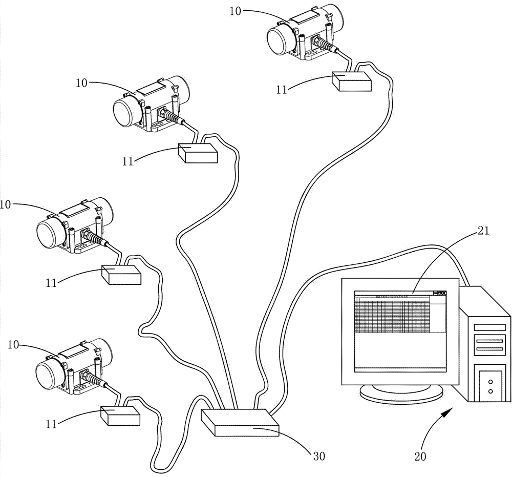
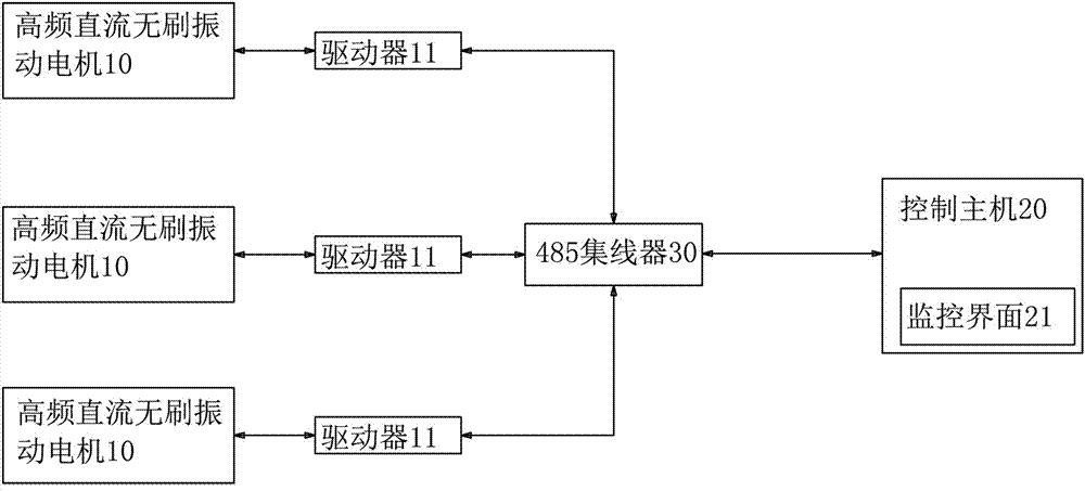
[0012] Figure 1 to Figure 2 , which is a preferred embodiment of a real-time centralized display monitoring system for a vibration motor in a PCB electroplating process provided by the present invention. Such as Figure 1 to Figure 2 As shown, the real-time centralized display monitoring system includes several electroplating equipment, and the hanger of each electroplating equipment is provided with a high-frequency DC brushless vibration motor 10, and the driver 11 of the high-frequency DC brushless vibration motor 10 is wired with the control host 20. Communication connection, the driver 11 receives the control signal sent by the control host 20, and feeds back the speed signal of the high-frequency brushless DC vibration motor 10 to the control host 20 in real time; The monitoring interface 21 of the rotating speed of the vibrating ...


PUM


Abstract

The invention provides a real-time display monitoring system of vibration motor during a PCB electroplating process, and belongs to the PCB electroplating field. The real-time display monitoring system of vibration motor during a PCB electroplating process includes a plurality of electroplating devices; each electroplating device includes a plurality of electroplating devices; a hanger of each electroplating device is provided with a high frequency direct current brushless vibration motor; a driver of the high frequency direct current brushless vibration motor is in wired communication connection with a control host; the driver receives a control signal sent from the control host, and feeds back a rotating speed signal of the high frequency direct current brushless vibration motor to the control host in real time; and the control host includes a monitoring interface for integratedly displaying the rotating speed of each high frequency direct current brushless vibration motor. Compared with the prior art, the real-time display monitoring system of vibration motor during a PCB electroplating process integratedly display the operating situation of the vibration motors of the plurality of electroplating devices on the monitoring interface, so that a work staff can monitor the operating situation of each motor at any time and can timely adjust the rotating speed of each motor so as to timely solve the problem timely that the waste board rate and reject rate of PCB are generated because the vibration intensity of the motors cannot reach the standard.

Description

technical field [0001] The invention relates to the field of PCB electroplating, in particular to a real-time centralized display monitoring system of a vibration motor in the PCB electroplating process. Background technique [0002] At present, in the PCB electroplating process, the PCB board is placed in the hanger, and the vibration motor needs to be used to vibrate the hanger to make the PCB board shake in the potion, so that no air bubbles are generated on the PCB board, and the PCB board plating effect is good. However, in the existing electroplating process, due to the need to use multiple vibration motors for vibration at the same time, and lack of real-time monitoring of the vibration intensity and amplitude of the vibration motors during the vibration process, the staff cannot monitor the vibration of each vibration motor in real time And the display, resulting in the PCB board hole break during the electroplating process, the hole filling rate of the potion is not...

Claims


Application Information

Patent Timeline
IPC IPC(8): G01R31/34
CPCG01R31/343
Inventor 王新祥
Owner 深圳市欣佳宏科技有限公司
Why Eureka
Try Eureka