A kind of anti-glare cover plate and its manufacturing method

A manufacturing method and cover technology, which are applied in optics, optical components, nonlinear optics, etc., can solve problems such as changes in image quality and content, loss of information, etc., and achieve the effects of reducing flashing phenomena and enhancing outdoor readability

Active Publication Date: 2019-09-13
WUHAN CHINA STAR OPTOELECTRONICS TECH CO LTD
View PDF7 Cites 0 Cited by
  • Summary
  • Abstract
  • Description
  • Claims
  • Application Information

AI Technical Summary

Problems solved by technology

[0007] The object of the present invention is to provide an anti-glare cover plate and its manufacturing method to solve the problem in the prior art that due to the light scattering effect caused by the uneven surface of the cover plate, the image quality information will appear after entering the human vision. The loss or increase is the problem of the change of the picture quality content

Method used


Image

  • A kind of anti-glare cover plate and its manufacturing method
  • A kind of anti-glare cover plate and its manufacturing method
  • A kind of anti-glare cover plate and its manufacturing method

Examples


Embodiment 1

[0038] Please refer to Figure 7 , Figure 7 It is a top view of the overall structure of an anti-glare cover plate of this embodiment. An anti-glare cover plate of the present invention is used to cover a liquid crystal display panel, from Figure 7 It can be seen that it includes a transparent cover body 10, and a plurality of anti-glare units 20 are provided on the side of the cover body 10 facing away from the liquid crystal display panel.

[0039] The plurality of anti-flash units 20 are arranged in an array, and when the cover body 10 is bonded to the liquid crystal display panel, the plurality of anti-flash units 20 and the plurality of sub-pixel units of the liquid crystal display panel In one-to-one correspondence, the area of ​​each anti-flash unit 20 is the same as the area of ​​a corresponding sub-pixel unit.

[0040] Wherein, each of the anti-flash units 20 is provided with a plurality of light-transmitting microstructures 30, and the plurality of microstructur...

Embodiment 2

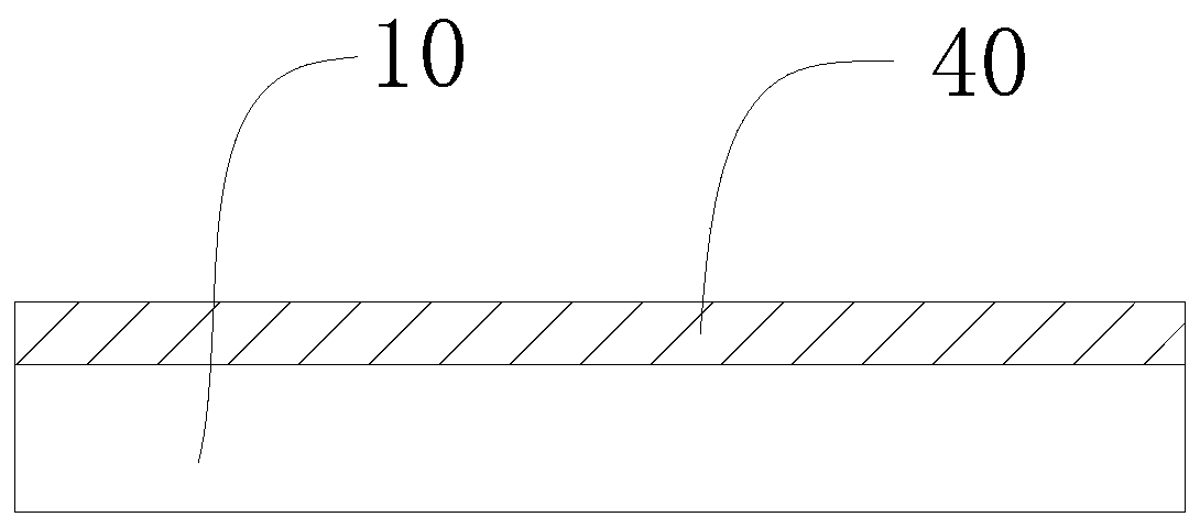
[0049] Please refer to Figure 1 to Figure 6 , figure 1 It is a schematic diagram of coating a transparent organic material layer 40 on a glass substrate in the implementation steps of an anti-glare cover plate manufacturing method according to an embodiment of the present invention;

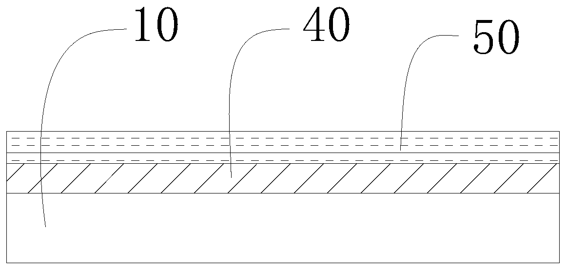
[0050] figure 2 It is a schematic diagram of coating a photoresist layer 50 on the transparent organic material layer 40 in the implementation steps of a method for manufacturing an anti-glare cover plate according to an embodiment of the present invention;

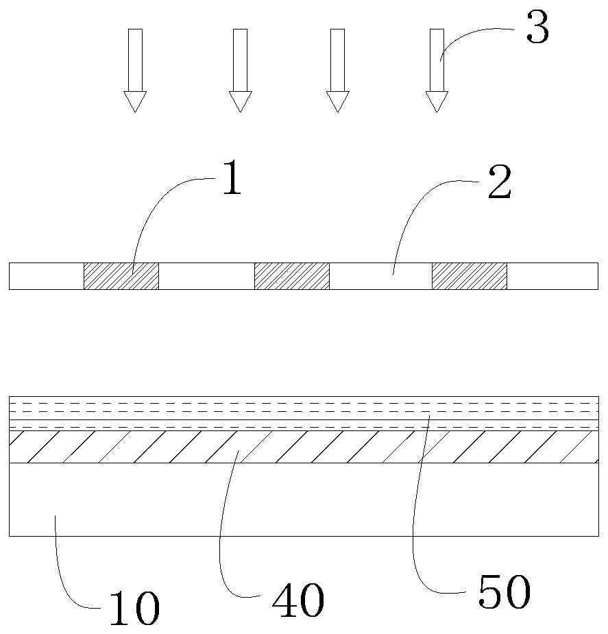
[0051] image 3 It is a schematic diagram of irradiating ultraviolet light 3 on the set photomask in the implementation steps of a method for manufacturing an anti-glare cover plate according to an embodiment of the present invention;

[0052] Figure 4 It is a schematic diagram of the photoresist layer 50 forming the shapes of the multiple microstructures 30 on the multiple anti-glare units 20 during the implementation steps of the me...


PUM


Abstract

The invention provides an anti-flashing cover plate. The anti-flashing cover plate comprises a transparent cover plate body, and the face, opposite to the liquid crystal display panel, of the transparent cover plate body is provided with multiple anti-flashing units; the multiple anti-flashing units are distributed in an array mode, when the cover plate and the liquid crystal display panel are connected, the multiple anti-flashing units correspond to multiple sub-pixel units of the liquid crystal display panel one-to-one, and the area of each anti-flashing unit is the same as that of the corresponding sub-pixel unit, wherein each anti-flashing unit is provided with multiple light transmitting microstructures, the multiple light transmitting microstructures are arranged in an unordered mode, and when light rays of the liquid crystal display panel emerges to the anti-flashing units, the anti-flashing units can avoid the problem of the occurrence of flashing of the light rays on the surface of the cover plate body. According to the anti-flashing cover plate, the cover plate makes the phenomenon of flashing avoided, and the effect of strengthening outdoor readability is achieved.

Description

[0001] 【Technical field】 [0002] The invention relates to the field of liquid crystal display, in particular to an anti-glare cover plate and a manufacturing method thereof. [0003] 【Background technique】 [0004] A liquid crystal display (LCD, Liquid Crystal Display) has many advantages such as a thin body, power saving, and no radiation, and has been widely used. TFT-LCD has been very popular in daily life, such as TV, computer, mobile phone and other display screens. The technology in this field is constantly updated to better serve consumers. Continuous product upgrades have made higher requirements for TFT-LCD and put forward higher requirements for product quality. [0005] With the increasing development of on-board display, more and more on-board display technologies have been developed, among which the anti-glare treatment on the surface of on-board equipment has aroused people's widespread interest. The development of AG (anti-glare, anti-glare) processing technol...

Claims


Application Information

Patent Timeline
Patent Type & Authority Patents(China)
IPC IPC(8): G02F1/1333G02F1/1335G02B1/10
CPCG02B1/10G02F1/133308G02F1/133502G02F1/133331
Inventor 杨勇杨映保
Owner WUHAN CHINA STAR OPTOELECTRONICS TECH CO LTD
Why Eureka
Try Eureka