Projector

A projector and prism technology, applied in the field of projectors, can solve problems such as lack of convenience, volume limitation, loss of competitiveness, etc., and achieve the effect of space configuration and optical path design optimization and volume reduction.

Active Publication Date: 2017-06-27
QISDA OPTRONICS (SUZHOU) CO LTD +1
View PDF5 Cites 3 Cited by
  • Summary
  • Abstract
  • Description
  • Claims
  • Application Information

AI Technical Summary

Problems solved by technology

However, the digital micromirror device 10 rotating around a single axis in the traditional projector 1 can only accept incident light as an oblique incident light due to the limitation of physical characteristics.
Therefore, the total reflection prism group 11 is inclined at an angle (for example, 45 degrees) relative to the digital micromirror device 10, which will cause the volume of the traditional projector 1 to be limited. In today's pursuit of miniaturized projectors, the traditional projector 1 is too large The volume will lead to insufficient convenience and gradually lose competitiveness

Method used


Image

  • Projector
  • Projector
  • Projector

Examples


Embodiment Construction

[0023] In order to have a further understanding of the purpose, structure, features, and functions of the present invention, the following detailed descriptions are provided in conjunction with the embodiments.

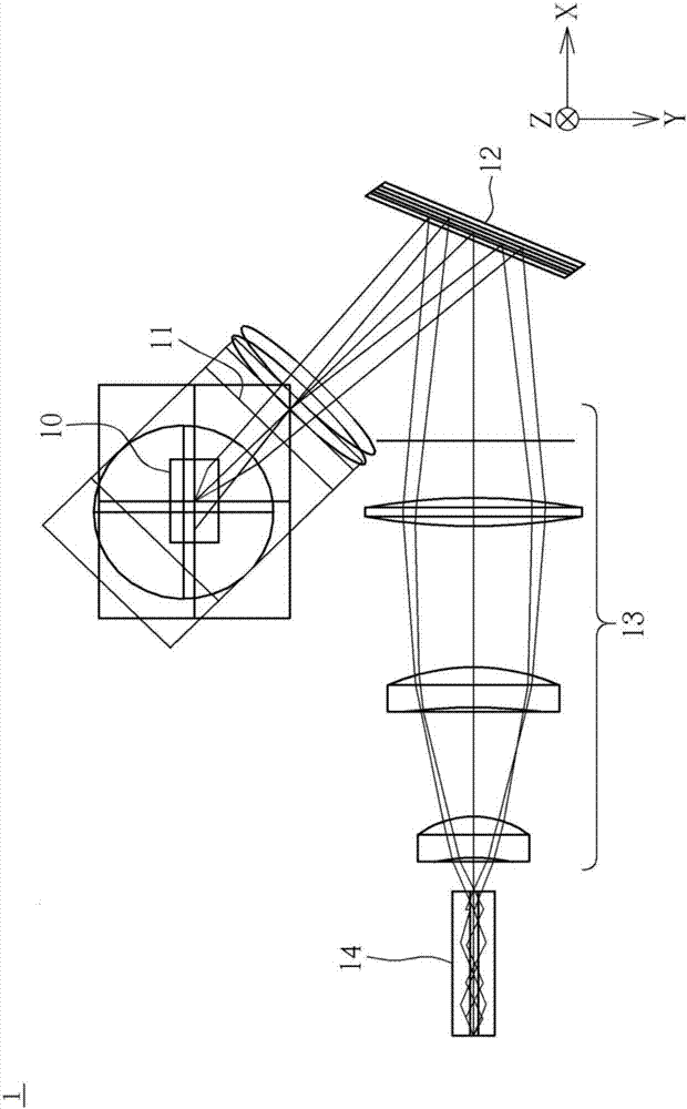
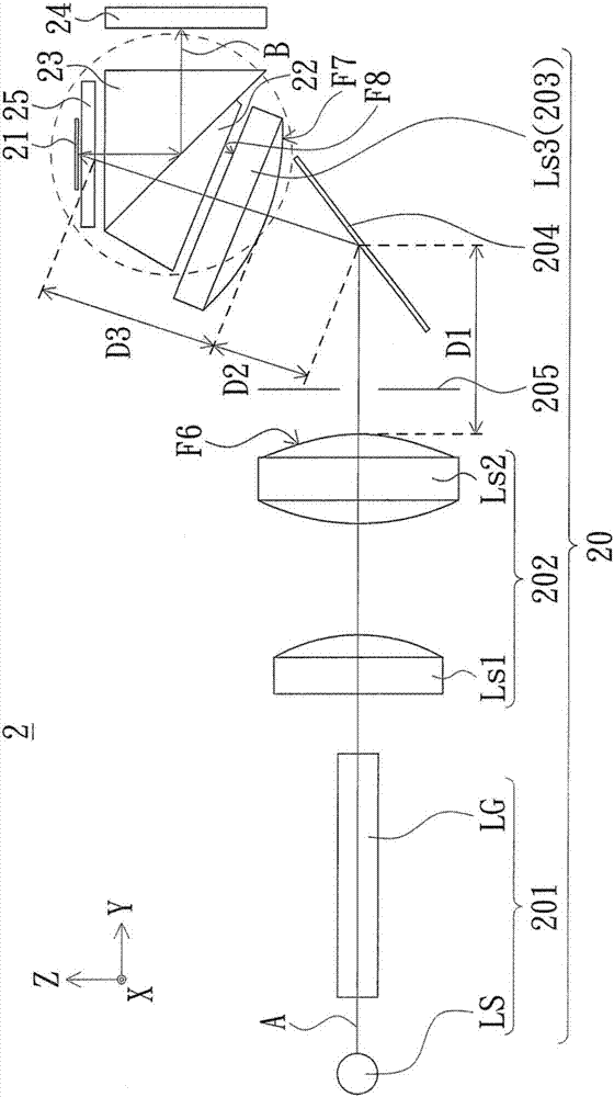
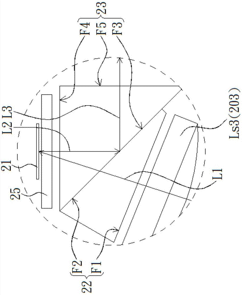
[0024] Please refer to Figure 2 to Figure 4 , figure 2 is a schematic diagram of the component structure of a projector according to an embodiment of the present invention, image 3 for figure 2 A partially enlarged schematic diagram of the projector component architecture shown, Figure 4 for figure 2 A schematic top view of the projector component architecture shown. Such as Figure 2 to Figure 4 As shown, the projector 2 of this embodiment includes an illumination system 20 , a two-axis flip digital micromirror device 21 , a first prism 22 , a second prism 23 and a lens 24 . The lighting system 20 is adapted to emit incident light A. As shown in FIG. The two-axis inverting digital micromirror device 21 is covered by a cover glass 25 and is suitable for r...


PUM


Abstract

The invention provides a projector comprising a lighting system, a biaxial overturning digital micromirror device, a first prism, a second prism, and a lens. The lighting system emits incident light. The digital micromirror device receives and converts the incident light into imaging light. The biaxial overturning digital micromirror device has two first opposite long sides and two first opposite short sides. The first prism is arranged between the lighting system and the biaxial overturning digital micromirror device and includes a first surface and a second surface. The second prism is arranged between the first prism and the biaxial overturning digital micromirror device and includes a third surface, a fourth surface and a fifth surface. The incident light is transmitted through the third surface and the fourth surface to the biaxial overturning digital micromirror device. The imaging light passes through the fourth surface, is reflected by the third surface and passes through the fifth surface to the lens. The fourth surface has two second opposite long sides and two second opposite short sides, the second long sides are parallel to the first long sides and the second short sides are parallel to the first short sides. The lens receives and projects the imaging light.

Description

technical field [0001] The present invention relates to a projector, in particular to a projector with a two-axis reversible digital micromirror device. Background technique [0002] The projector uses the imaging principle and uses a digital micro-mirror device (Digital Micro-mirror Device) to project tiny images onto a huge screen and provide enough brightness to share image information with everyone. [0003] figure 1 is a component architecture diagram of a traditional projector 1, such as figure 1 As shown, the conventional projector 1 includes a digital micromirror device 10 , a reflection (Total Internal Reflection, TIR) prism group 11 , a mirror 12 , a lens module 13 and a light pipe (Light Pipe) 14 . To define the view direction, figure 1 The right side of shows the three axes of the Cartesian coordinate system. by figure 1 Specifically, the X-axis is the direction to the right from the origin, the Y-axis is the downward direction from the origin, and the Z-axi...

Claims


Application Information

Patent Timeline
Patent Type & Authority Applications(China)
IPC IPC(8): G03B21/20G03B21/00G02B26/08
CPCG02B26/0833G03B21/008G03B21/2066
Inventor 简志雄林明坤
Owner QISDA OPTRONICS (SUZHOU) CO LTD
Why Eureka
Try Eureka