Composite cooling-type motor

A motor and cooling technology, applied in bearing cooling, electric components, electromechanical devices, etc., can solve the problems of inability to ensure the normal use of the front end cover and the bearing in the rear end cover, affecting the normal use of the bearing, and inability to cool the front end cover, etc. Improved cooling effect, improved reliability and service life, and easy maintenance

Inactive Publication Date: 2017-06-27
JIANGSU YUANDONG ELECTRIC MOTOR MFG
View PDF0 Cites 1 Cited by
  • Summary
  • Abstract
  • Description
  • Claims
  • Application Information

AI Technical Summary

Problems solved by technology

[0002] The existing motor combined base includes a front end cover, a housing, and a rear end cover. Bearings are installed in the front end cover and the rear end cover. When the motor is running, the bearings in the front end cover and the rear end cover generate a certain amount of heat. A large amount of heat is generated, which will increase the temperature of the bearings in the front end cover and rear end cover, affecting the normal use of the bearings
Therefore, the combined motor base of the prior art has taken certain cooling measures, such as the front end cover, the housing, and the rear end cover are all provided with an inner cavity interlayer, and after being connected, a cooling water channel is formed to cool the front end cover and the rear end cover. Bearings are cooled. This motor combined frame can cool the bearings in the front end cover and rear end cover to a certain extent. However, if the motor load is relatively large and the heat generated is relatively large, this motor combined frame cannot Sufficient cooling of the bearings in the front end cover and rear end cover cannot guarantee the normal use of the bearings in the front end cover and rear end cover

Method used


Image

  • Composite cooling-type motor
  • Composite cooling-type motor
  • Composite cooling-type motor

Examples


Embodiment Construction

[0026] The present invention will be further described below according to the accompanying drawings and in conjunction with the embodiments.

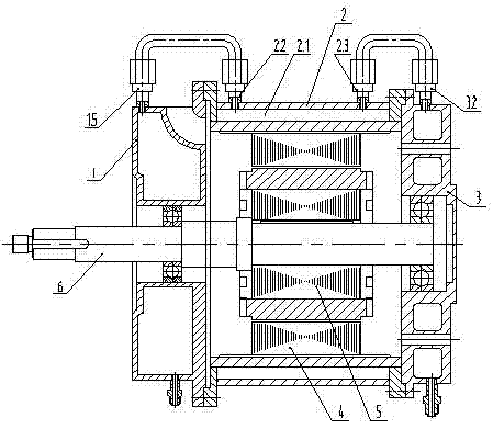
[0027] The composite cooling motor shown in the accompanying drawings includes a front end cover 1 , a housing 2 and a rear end cover 3 .

[0028] The housing 2 is provided with an inner cavity interlayer II 2.1, and the outer wall of the housing 2 is provided with a water inlet joint II 2.2 and an outlet joint II 2.3 communicating with the inner cavity interlayer II 2.1.

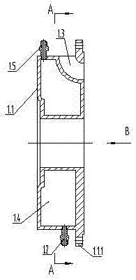
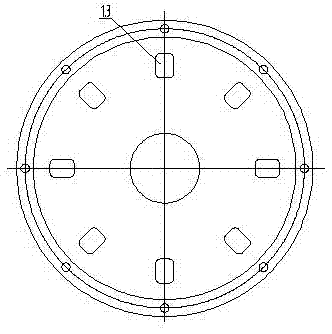
[0029] The front end cover 1 includes a disc body I1.1 with an inner cavity interlayer I1.4; a bearing hole is provided in the middle of the disc body I1.1, and the outer wall part of the right end extends radially outward to form a flange edge I1.1.1; the disc body I1.1. 1 The outer wall is provided with water inlet joint I1.2 and water outlet joint I1.5, and the inner holes of water inlet joint I1.2 and water outlet joint I1.5 are respectively connected with the in...


PUM


Abstract

The invention discloses a composite cooling motor, which comprises a front end cover, a casing and a rear end cover; the front end cover, the casing and the rear end cover are all provided with a cooling water channel formed by an inner cavity interlayer, a water inlet joint and a water outlet joint; the rotor It is a copper rotor; its improvement is: there is a cooling air passage Ⅰ in the front end cover, a cooling air passage Ⅲ in the rear end cover, and the combination of the cooling air passage Ⅰ in the front end cover, the inner cavity of the shell, and the cooling air passage Ⅲ in the rear end cover into a motor cooling air duct; further improvement lies in: the water outlet joint Ⅰ on the front cover is connected with the water inlet joint Ⅱ on the outer wall of the housing through the pipeline, and the water outlet joint Ⅱ on the outer wall of the housing is connected with the water inlet joint Ⅲ on the rear end cover through the pipeline ; The rotor is a cast copper rotor. The invention has high efficiency and good reliability.

Description

technical field [0001] The invention relates to the technical field of motors, in particular to a combined motor base. Background technique [0002] The existing motor combined base includes a front end cover, a housing, and a rear end cover. Bearings are installed in the front end cover and the rear end cover. When the motor is running, the bearings in the front end cover and the rear end cover generate a certain amount of heat. A large amount of heat is generated, which will increase the temperature of the bearings in the front end cover and the rear end cover, affecting the normal use of the bearings. Therefore, the combined motor base of the prior art has taken certain cooling measures, such as the front end cover, the housing, and the rear end cover are all provided with an inner cavity interlayer, and after being connected, a cooling water channel is formed to cool the front end cover and the rear end cover. Bearings are cooled. This motor combined frame can cool the ...

Claims


Application Information

Patent Timeline
Patent Type & Authority Applications(China)
IPC IPC(8): H02K5/20H02K5/16H02K1/26H02K1/28F16C37/00
CPCH02K5/20F16C37/00H02K1/26H02K1/265H02K1/28H02K5/161
Inventor 俞志君巫进王浩亮张新曹正海
Owner JIANGSU YUANDONG ELECTRIC MOTOR MFG
Why Eureka
Try Eureka