Spring leaf-type bistable electromagnetic piezoelectric composite energy collecting device

A technology of piezoelectric compounding and energy harvesting, applied in electromechanical devices, generators/motors, piezoelectric effect/electrostrictive or magnetostrictive motors, etc., can solve the problem of narrow operating frequency band of energy harvesters and limited power generation efficiency, etc. problem, to achieve the effect of improving energy harvesting efficiency, enhancing piezoelectric effect, and increasing electromagnetic induction effect

Active Publication Date: 2017-06-27
HEFEI UNIV OF TECH
View PDF4 Cites 25 Cited by
  • Summary
  • Abstract
  • Description
  • Claims
  • Application Information

AI Technical Summary

Problems solved by technology

However, the vibration in the natural environment is often random vibration with a wide frequency band. The working frequency band of the energy harvester is narrow, and the power generation efficiency is very limited.

Method used


Image

  • Spring leaf-type bistable electromagnetic piezoelectric composite energy collecting device
  • Spring leaf-type bistable electromagnetic piezoelectric composite energy collecting device
  • Spring leaf-type bistable electromagnetic piezoelectric composite energy collecting device

Examples


Embodiment 1

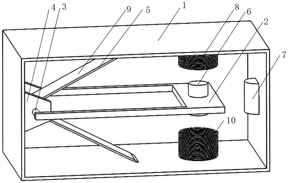
[0034] see figure 1 , a spring leaf type bistable electromagnetic piezoelectric composite energy harvesting device includes a static mechanism and a dynamic mechanism.

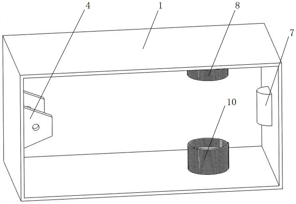
[0035] see figure 2 , the static mechanism includes a box-type casing 1, a bearing support 4 is installed in the middle of one side of the casing 1, and a columnar fixed magnet 7 is installed in the middle of the opposite side; the casing 1 adjacent to the fixed magnet 7 An upper coil 8 is installed on the inner top, and a lower coil 10 is installed on the inner bottom, and the upper coil 8 and the lower coil 10 correspond up and down. The material of the casing 1 is aluminum, and the inner top wall and the inner bottom wall of the casing 1 are respectively provided with insulating layers, so as to avoid conduction with the upper coil 8 and the lower coil 10 .

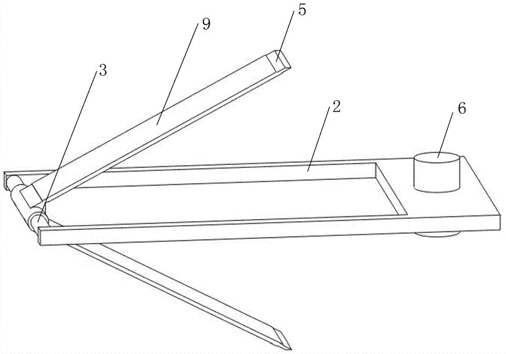
[0036] see image 3 , the dynamic mechanism includes a rectangular frame-type pendulum frame 2, and the material of the pendulum frame 2 is copper...

Embodiment 2

[0040] see Figure 5 , Figure 6 and Figure 7 , in this embodiment, three upper coils 8 are installed on the inner top of the casing 1 adjacent to the fixed magnet 7, and three lower coils 10 are installed on the inner bottom; three columnar vibrator magnets 6 are installed on the other end of the pendulum frame 2; Two ends of each vibrator magnet 6 correspond to three upper coils 8 and three lower coils 10 respectively. Other structures are the same as embodiment 1, and the working principle is the same as embodiment 1.

[0041] This embodiment uses three vibrator magnets 6, three upper coils 8 and three lower coils 10, which can greatly increase the electromagnetic power generation of the coils; on the other hand, since the number of vibrator magnets 6 has increased to three, the frame The sum of the repulsive force of the magnets on the 2 ends will also be doubled. Compared with Example 1, the upper stable position of the pendulum frame 2 during the vibration process w...


PUM


Abstract

The present invention relates to a spring leaf-type bistable electromagnetic piezoelectric composite energy collecting device, including a static mechanism and a movable mechanism. The static mechanism comprises a housing, and the housing is internally provided with a bearing bearer, a fixed magnet, an upper coil and a lower coil. The movable mechanism comprises a pendulum frame, a spring piece and a vibration magnet and a spring piece is a V-shaped or U-shaped sheet. In the natural state, the upper and lower ends of the spring piece are in contact with the inner top wall and the inner bottom wall of the housing respectively. The vibration magnet and the fixed magnet are magnetized in the axial direction and repel each other. Under the action of external vibration excitation, the swinging of the pendulum frame drives the rotation of a rotating shaft, and then the spring piece and a piezoelectric element are deformed and the electric charge is generated. The electric energy is outputted through an electrode terminal lead. When the vibration magnet on the pendulum frame swings up and down, the magnetic field around the magnet also moves, the coil in the magnetic field cuts the magnetic induction lines and generates induced current, and the current is output through the lead.

Description

technical field [0001] The invention belongs to the field of energy recovery, and mainly relates to a spring leaf type bistable electromagnetic piezoelectric composite energy collection device. Background technique [0002] In recent years, with the construction of smart cities, the monitoring of environmental problems and the construction of the Internet of Things, the wireless sensor network technology based on MEMS sensors, wireless communication and embedded control systems has developed rapidly. However, making wireless sensor network nodes in a maintenance-free operating state for a long time has become a bottleneck to further promote its application. As a common phenomenon in nature, vibration is almost everywhere and has a high energy density. Vibration energy harvesting technology can convert the vibration energy in the surrounding environment into usable electrical energy, and can effectively realize the self-power supply of wireless sensor network nodes, which ha...

Claims


Application Information

Patent Timeline
Patent Type & Authority Applications(China)
IPC IPC(8): H02N2/18H02K35/02
CPCH02K35/02H02N2/186
Inventor 邓华夏杜宇王哲敏于连栋张进马孟超钟翔
Owner HEFEI UNIV OF TECH
Why Eureka
Try Eureka