Crank and connecting rod type electromagnetic piezoelectric composite energy collecting device

A crank connecting rod and piezoelectric composite technology, which is applied in electromechanical devices, generators/motors, piezoelectric effect/electrostrictive or magnetostrictive motors, etc., can solve the problem of limited vibration amplitude of piezoelectric double crystal beams, pressure The deformation of electrical components is not large, the change of magnetic flux is not obvious, etc., to achieve the effect of improving wind power generation efficiency, increasing the rate of change of magnetic flux, and wide application range

Active Publication Date: 2017-06-13
HEFEI UNIV OF TECH
View PDF6 Cites 6 Cited by
  • Summary
  • Abstract
  • Description
  • Claims
  • Application Information

AI Technical Summary

Problems solved by technology

Although the structure uses both electromagnetic and piezoelectric effects to generate electricity; however, the piezoelectric bicrystal beam mainly relies on the vibration excitation in the external environment to generate vibration. Large vibrations can only be generated when the frequency is close, and the vibration in the natural environment is often low-frequency random vibration, so the vibration amplitude of the piezoelectric bicrystalline beam in this device is very limited, and the deformation of the piezoelectric element is not large. weak effect
At the same time, the relative displacement between the magnet block at the end of the piezoelectric bicrystalline beam and the multi-turn coils on both sides is also small, the change of magnetic flux is not obvious, and the efficiency of electromagnetic power generation is also low.

Method used


Image

  • Crank and connecting rod type electromagnetic piezoelectric composite energy collecting device
  • Crank and connecting rod type electromagnetic piezoelectric composite energy collecting device
  • Crank and connecting rod type electromagnetic piezoelectric composite energy collecting device

Examples


Embodiment 1

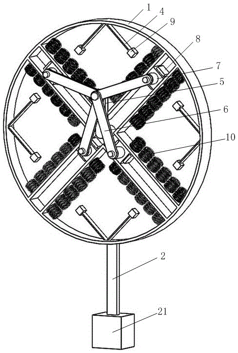
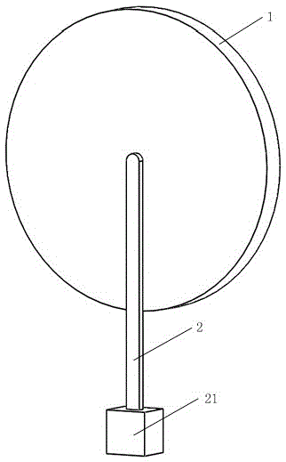
[0038] see figure 1 and figure 2 A crank-link electromagnetic piezoelectric composite energy harvesting device includes a chassis 1, a crank-link slider mechanism, a rotary input mechanism, and an electromagnetic piezoelectric mechanism.

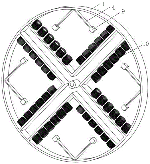
[0039] see image 3 , one side of the chassis 1 is provided with four radial chutes, and one end of the four chutes converges at the center of the chassis 1 . A shaft cylinder is arranged in the axial direction of the center of the chassis 1 ; a frame is arranged on the outer circumference of the chassis 1 . The material of the chassis and the chute is aluminum.

[0040] see Figure 4 and Figure 6 , The crank-link slider mechanism includes a crank 5, four connecting rods 6 and four sliders 7. One end of the four connecting rods 6 is connected to a slide block 7 for corresponding rotation respectively, and the other end of the four connecting rods 6 is respectively rotated and connected to one end of the crank 5, and the other end of ...

Embodiment 2

[0045] see Figure 7 , Figure 8 and Figure 9 , the rotation input mechanism is a turning wheel mechanism, and the turning wheel mechanism includes a cutting water wheel 11, and the cutting water wheel 11 is connected to the other end of the crank 5 through the rotating shaft 3.

[0046] Other structures are with embodiment 1.

[0047] During work, when fluid flows from the side of the cutting water wheel 11, the rotation of the cutting water wheel 11 drives the crank 5 to rotate through the rotating shaft 3, and other working principles are the same as in the first embodiment.

Embodiment 3

[0049] see Figure 10 and Figure 11 , One side of the chassis 1 is provided with five radial slide grooves; the crank-link slider mechanism includes a crank 5, five connecting rods 6 and five sliders 7.

[0050] Other structures are with embodiment 1.

[0051] Working principle is the same as embodiment 1.


PUM


Abstract

The invention relates to a crank and connecting rod type electromagnetic piezoelectric composite energy collecting device. The crank and connecting rod type electromagnetic piezoelectric composite energy collecting device comprises a bottom disc, a crank, connecting rod and slide block mechanism, a rotary input mechanism and an electromagnetic piezoelectric mechanism, wherein four slide grooves or more are arranged at one side surface of the bottom disc in a radial way, and one end of the four slide grooves or more is gathered at the center of the bottom disc; the crank, connecting rod and slide block mechanism comprises a crank, four connecting rods or more and slide blocks, and the slide blocks are respectively and correspondingly positioned in four slide grooves or more; the rotary input mechanism is positioned at the other side surface of the bottom disc, and is a mass swing rod mechanism or a rotary wheel mechanism; the electromagnetic piezoelectric mechanism comprises four piezoelectric bimorph beam mechanisms or more, four magnets or more and coils, and the coils are uniformly arranged at both sides of each slide groove. The crank and connecting rod type electromagnetic piezoelectric composite energy collecting device has the advantages that under the action of outside excitation, the rotary input mechanism is used for driving the magnets to do reciprocating movement in the slide grooves, and the multiple coils can produce and output sensing current; the piezoelectric bimorph beam mechanisms can generate larger vibration and bending deformation, and produce and output charges.

Description

technical field [0001] The invention belongs to the technical field of energy recovery, and relates to an electromagnetic piezoelectric composite energy conversion technology, in particular to a crank connecting rod type electromagnetic piezoelectric composite energy collection device. Background technique [0002] The modernization of the world economy has benefited from the wide application of fossil energy, such as oil, natural gas, coal, etc., so it is an economy based on fossil energy. Extensive use of fossil energy will increase carbon emissions and intensify the greenhouse effect. At the same time, once the chain of fossil energy and raw materials is interrupted, it will inevitably lead to the intensification of the world economic crisis and conflicts, and lead to the outbreak of the energy crisis. In today's increasingly serious energy shortage, it is of great significance to replace traditional fossil energy with clean and renewable energy. [0003] Energy harvest...

Claims


Application Information

Patent Timeline
Patent Type & Authority Applications(China)
IPC IPC(8): H02K7/18H02N2/18
CPCH02K7/1876H02N2/185
Inventor 邓华夏杜宇王哲敏于连栋张进马孟超钟翔
Owner HEFEI UNIV OF TECH
Why Eureka
Try Eureka