Dual-beam mutually excited multistable frequency-raising vibration energy collecting device

A vibration energy harvesting and multi-stable technology, applied in the direction of generators/motors, piezoelectric effect/electrostrictive or magnetostrictive motors, electrical components, etc., can solve low-frequency resonance obstacles, complex magnetic field settings, and low utilization Low-level problems, to achieve the effect of reducing difficulty, improving energy collection efficiency, and improving magnetic field utilization

Inactive Publication Date: 2018-05-08
TIANJIN UNIV
View PDF6 Cites 6 Cited by
  • Summary
  • Abstract
  • Description
  • Claims
  • Application Information

AI Technical Summary

Problems solved by technology

[0003] In order to overcome the hindrance effect of the outer potential well on the low-frequency resonance of the existing broadband multi-stable up-frequency vibration energy harvester, improve the defects of complicated magnetic field setting, low utilization rate, and inability to further miniaturize, and further improve the performance of the harvester in small excitation Under the output effect, the present invention provides a dual-beam mutual excitation broadband multi-stable up-frequency vibration energy harvester, which can prevent the cantilever beam oscillator from falling into a certain outer potential well through the mutual excitation of two driving cantilever beams The failure phenomenon of vibration energy harvester caused by

Method used


Image

  • Dual-beam mutually excited multistable frequency-raising vibration energy collecting device
  • Dual-beam mutually excited multistable frequency-raising vibration energy collecting device
  • Dual-beam mutually excited multistable frequency-raising vibration energy collecting device

Examples


Embodiment Construction

[0016] The technical solutions of the present invention will be further described below in conjunction with specific embodiments.

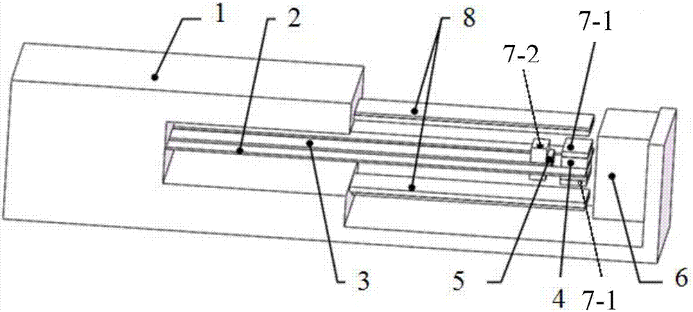
[0017] Referring to the accompanying drawings, the double-beam mutual excitation broadband multi-stable up-frequency vibration energy harvester in the present invention includes a housing 1, a driving cantilever beam I2, a driving cantilever beam II3, a NdFeB permanent magnet I4, and a NdFeB permanent magnet Ⅱ5, NdFeB permanent magnet Ⅲ6, two high-frequency piezoelectric cantilever beams 8, and counterweights;

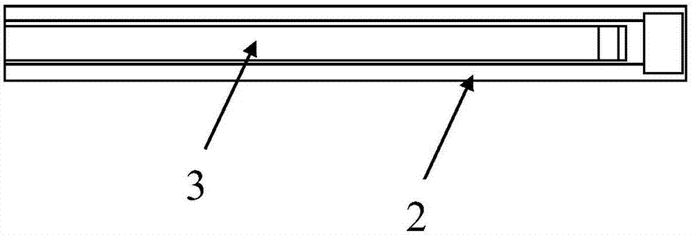
[0018] The driving cantilever beam I2 is C-shaped, that is, one end of the driving cantilever beam I2 is open and a through slot for accommodating the driving cantilever beam II3 is provided extending from the opening end to the other end, and the opening end of the driving cantilever beam I2 is fastened on On the shell 1, the other end is fixed with a counterweight 7-1 used as an inertial mass and a NdFeB permanent magnet I4; the driving ...


PUM


Abstract

The invention discloses a dual-beam mutually excited multistable frequency-raising vibration energy collecting device, which comprises a shell, a driving cantilever beam I, a driving cantilever beam II and two high-frequency piezoelectric cantilever beams, wherein one end of the driving cantilever beam I is open, the driving cantilever beam I is provided with a through slot used for accommodatingthe driving cantilever beam II in a mode of extending from the open end to the other end, the open end of the driving cantilever beam I is fastened on the shell, and the other end is fixedly providedwith a counterweight block and a rubidium ferrum boron permanent magnet I; the driving cantilever beam II is located inside the through slot of the driving cantilever beam I, one end of the driving cantilever beam II is fastened on the shell, and the other end is fixedly provided with a counterweight block and a rubidium ferrum boron permanent magnet II; the two high-frequency piezoelectric cantilever beams are symmetrically arranged at two sides of a neutral surface of the driving cantilever beam I and are fixed through the shell; and a rubidium ferrum boron permanent magnet III is fixed on the shell in the extending direction of the outer end of the driving cantilever beam I. According to the invention, a cantilever beam vibrator can be avoided from being caught in a certain outer potential well to result in failure of the vibration energy collecting device through mutual excitation of the two driving cantilever beams.

Description

technical field [0001] The invention belongs to the technical field of vibration energy collection, and in particular relates to a double-beam mutual excitation broadband multi-stable up-frequency vibration energy collector. Background technique [0002] At present, most of the known broadband multi-stable up-frequency piezoelectric vibration energy harvesters use a low-frequency vibrator to couple the vibration in the environment, and then transfer the kinetic energy of the low-frequency vibrator to the piezoelectric single chip with high natural frequency through collision or magnetic force. The cantilever beam, in turn, generates electricity through electromechanical coupling. The multi-stable characteristics of the collector mainly depend on the external magnetic field. When the steady-state number reaches three or more, at least two external independent magnets are required to form the desired magnetic field. From the perspective of the form of system potential energy...

Claims


Application Information

Patent Timeline
Patent Type & Authority Applications(China)
IPC IPC(8): H02N2/18
Inventor 张琪昌王辰王炜赵开元
Owner TIANJIN UNIV
Why Eureka
Try Eureka