
Integrated doffing device of spinning frame

A spinning frame and collective technology is applied in the field of improvement of the structure of the collective doffing device of the spinning frame, which can solve the problems of prolonging the doffing time, complicated action process, occupying space, etc. The effect of high motion accuracy

Inactive Publication Date: 2017-06-30
江苏海马纺织机械有限公司
View PDF7 Cites 2 Cited by
  • Summary
  • Abstract
  • Description
  • Claims
  • Application Information

AI Technical Summary

Problems solved by technology

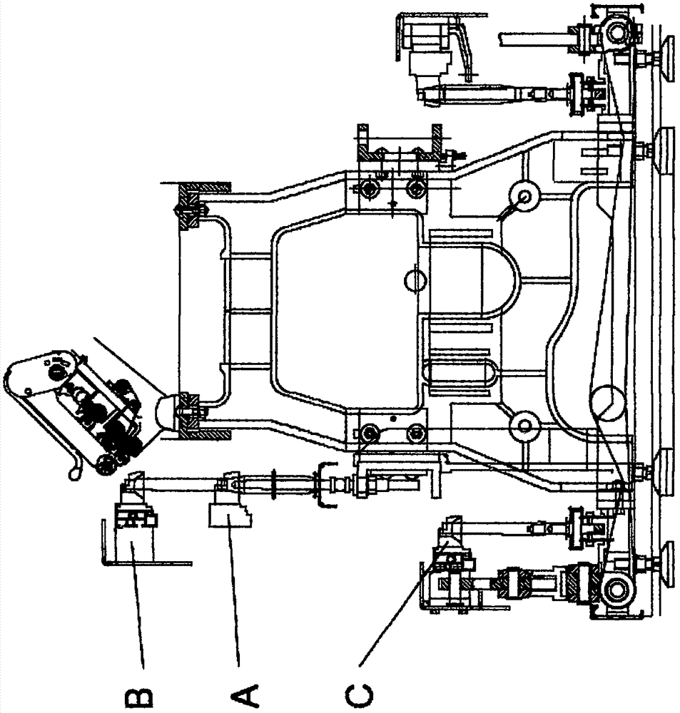
The collective doffing device of this structure requires strict action space and setting position during work. For example, it is necessary to ensure sufficient swing space for the doffing frame and herringbone linkage mechanism, and the center line of the bobbin conveying convex plate It must be located on the extension line of the center line of the spindle, so this structure can only be connected with the frame of the pre-designed spinning frame, and cannot be applied to the transformation of a large number of existing spinning frames without doffing devices. The scope of application is limited by the swing space, and it is necessary to set up an empty bobbin storage station at the position of the dragon tendon. Correspondingly, some intermediate transition links are added, which adds an unreliable factor and prolongs the doffing time, which not only increases The complexity of the structure of the doffing device makes the action process more complicated, which increases the problem of consistency control of the height of the doffing frame.
The existing spinning frame with collective doffing device has a wider fuselage, takes up more space, and brings inconvenience to the operator

Method used

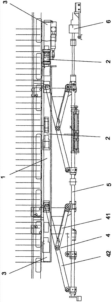

Image

  • Integrated doffing device of spinning frame
  • Integrated doffing device of spinning frame
  • Integrated doffing device of spinning frame

Examples


Embodiment Construction

[0014] The specific content of the present invention will be described in detail below in conjunction with the accompanying drawings and specific embodiments.

[0015] Such as figure 1 As shown, a spinning frame collective doffing device includes a yarn holder beam 1, a rotating wall 2, a holding beam 3, a herringbone lifting linkage mechanism 4, a lifting pull rod 5, and a pull rod driving device 6. The yarn holding device beam 1 extends from the head to the rear of the spinning frame, and the length of the yarn holding device beam 1 corresponds to the spindles on one side of the spinning frame. There is a hinged rotating arm 2 on the outside of the beam 1 of the yarn holding device. The rotating arm 2 consists of at least two groups, one of which is driven by a cylinder as the main arm, and the other as the slave arm. The rotating arm is used to control the yarn holding One section of the pivoting arm 2 is hinged on the yarn holder beam 1, and the other end is hinged on the...


PUM


Abstract

The invention discloses an integrated doffing device of a spinning frame. The integrated doffing device comprises a yarn-holding device beam, rotary arms, holding beams, inverted-V-shaped lifting link mechanisms, a lifting pull rod and a pull rod driving device. The rotary arms are hinged to the yarn-holding device beam, and the inverted-V-shaped lifting link mechanisms are hinged to the holding beams. The rotary arms are hinged to the outer side of the yarn-holding device beam and used for controlling horizontal movement of the yarn-holding device beam and avoiding outward-swinging action of the yarn-holding device beam. The inverted-V-shaped lifting link mechanisms are hinged to the inner sides of the holding beams. When bobbins are pulled out from or inserted into the doffing device, a lifting beam and a corresponding bobbin intermediate station are omitted, the intermediate transition action step executed when the bobbins are pulled out or inserted into is omitted, doffing time is shortened, higher production efficiency and action accuracy are achieved, and the accuracy when the bobbins are pulled out or inserted into is ensured.

Description

technical field [0001] The invention relates to a cotton spinning frame, in particular to an improvement of the structure of a collective doffing device of the spinning frame. Background technique [0002] Cotton spinning frame is an important process equipment with large volume and wide area in the cotton spinning production process. Spinning frame equipped with collective doffing device is an important link for cotton spinning enterprises to improve labor productivity; it is the development trend of textile production at present. Compared with the traditional manual bobbin doffing, the cotton thread reduces the labor intensity of the operator, significantly improves the environment and saves a lot of labor. [0003] The existing collective doffing device of the spinning frame mainly includes a doffing frame with a yarn holder fixedly installed therein, and a herringbone linkage mechanism for hingedly supporting the doffering frame. Each yarn holder on the doffing frame c...

Claims


Application Information

Patent Timeline
Patent Type & Authority Applications(China)
IPC IPC(8): D01H9/04
CPCD01H9/04
Inventor 陆立秋
Owner 江苏海马纺织机械有限公司
Learn More