
Concrete slab and preparation method thereof

A technology for concrete slabs and slabs, which is applied to pavement, roads, and pavement details paved with prefabricated blocks. It can solve the problems of affecting construction quality, deep cutting depth, and difficulty in cutting to the end, so as to simplify the cutting process and improve the quality. , good quality effect

Active Publication Date: 2017-06-30
皇玉彬
View PDF9 Cites 0 Cited by
  • Summary
  • Abstract
  • Description
  • Claims
  • Application Information

AI Technical Summary

Problems solved by technology

First, the cutting depth is deep, which is time-consuming and laborious; second, it is difficult to cut to the end, which affects the construction quality
[0003] This shows that the method for above-mentioned existing concrete slab cutting seam obviously still has inconvenience and defective, and demands urgently further improving

Method used


Image

  • Concrete slab and preparation method thereof
  • Concrete slab and preparation method thereof
  • Concrete slab and preparation method thereof

Examples


Embodiment 1

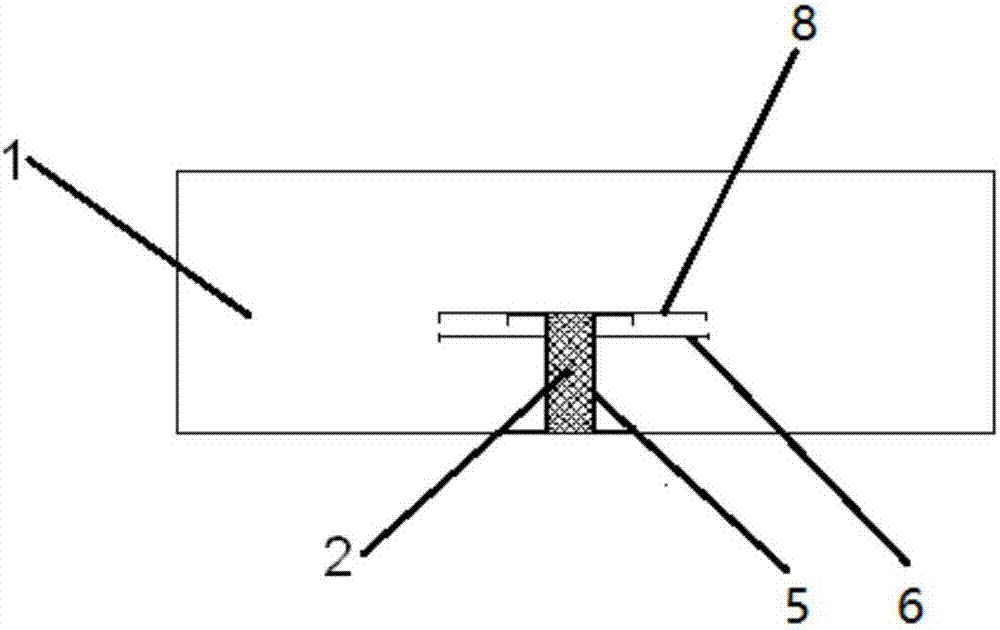
[0033] Refer to attached figure 1 As shown, the concrete slab 1 of the present invention includes invisible expansion and deformation joints 2 , and the invisible expansion and deformation joints 2 extend from the bottom to the top of the concrete slab 1 and do not reach the top of the concrete slab 1 . That is to say, the lower part of the concrete slab 1 is provided with invisible expansion and deformation joints, and the upper part of the concrete slab is a complete concrete surface, and no joint gaps can be seen on the top of the concrete slab.

[0034] Wherein, the height of the invisible expansion deformation joint 2 is less than or equal to 1 / 2 of the height of the concrete slab 1, and its width is 1-4 cm.

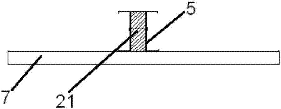
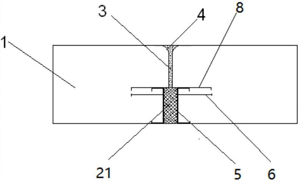
[0035] Refer to attached figure 2 As shown, in this embodiment, the invisible expansion and deformation joint 2 is filled with a stretchable board 21, and the stretchable board 21 is made of polyplastic board, polypropylene board, extruded board or polystyrene boa...

Embodiment 2

[0042] The difference between the second embodiment and the first embodiment above is that the invisible expansion deformation joint 2 is a cavity supported by a supporting template 22, and the supporting template 22 is made of steel plate or plastic material. Figure 4 shown. When cutting the top of the concrete slab, only need to cut and cut the top of the support template 22, the function of the invisible expansion deformation joint can be realized. Other parts or structures are the same as those in Embodiment 1, and will not be repeated here.

[0043] The preparation method of the above-mentioned concrete slab 1 with invisible expansion deformation joint 2 comprises the following steps:

[0044] (1) A cushion of suitable size is preset according to the size of the pre-prepared concrete slab, and the position of the invisible expansion deformation joint is arranged on the cushion;

[0045] (2) Fix the support formwork 22 or the stretchable plate 21 at the position of the ...


PUM


Abstract

The invention discloses a concrete slab. The concrete slab comprises an invisible swelling deformation joint. The invisible swelling deformation joint stretches from the bottom to the top of the concrete slab and does not reach the top of the concrete slab. The height of the invisible swelling deformation joint is smaller than or equal to 1 / 2 that of the concrete slab. The invisible swelling deformation joint is filled with a telescopic board or a cavity formed by supporting of a supporting formwork. C-shaped fixing plates are arranged on the two sides of the telescopic board or the supporting formwork, and multiple through holes are formed in the tops of the C-shaped fixing plates. The invention further discloses a preparation method of the concrete slab with the invisible swelling deformation joint. The invisible swelling deformation joint is formed in the lower portion of the concrete slab, preparation of the large-size concrete slab is not affected, the integrity of the concrete slab is guaranteed, cutting of a cutting joint during application of the concrete slab is promoted, cutting procedures are simplified and convenient, and the quality of the concrete slab is further improved by arranging horizontal dowel bars and connecting ribs in the concrete slab.

Description

technical field [0001] The invention relates to the technical field of concrete slab preparation, in particular to a concrete slab and a preparation method thereof. Background technique [0002] Due to changes in temperature throughout the year, the concrete slab will expand and shrink to varying degrees, resulting in excessive stress inside the concrete slab, resulting in fracture or arching of the concrete slab. In order to avoid this defect, the concrete slab will be provided with expansion joints and contraction joints during construction. At present, the setting of the expansion joints is to complete the complete cutting from top to bottom on the concrete pavement by the pavement cutting machine, and divide the whole concrete slab into many small concrete slabs. This one is that the cutting depth is deep, time-consuming and laborious, and the other is that it is difficult to cut to the end, which affects the construction quality. [0003] This shows that the above-men...

Claims


Application Information

Patent Timeline
Patent Type & Authority Applications(China)
IPC IPC(8): E01C5/00E01C11/00
CPCE01C5/00E01C11/00Y02W30/91
Inventor 皇玉彬
Owner 皇玉彬
Learn More