Supercharge Your Innovation With Domain-Expert AI Agents!

Route programming method and device for intelligent robot

An intelligent robot and path planning technology, applied in the field of intelligent robots, can solve problems such as poor stability and lack of open source code, and achieve the effect of improving stability

Active Publication Date: 2017-06-30
BEIJING GUANGNIAN WUXIAN SCI & TECH
View PDF8 Cites 9 Cited by
  • Summary
  • Abstract
  • Description
  • Claims
  • Application Information

AI Technical Summary

Problems solved by technology

However, the current visual SLAM algorithm is immature compared with the laser SLAM algorithm, and the open source code is relatively scarce, and its stability is far inferior to the laser SLAM algorithm.

Method used


Image

  • Route programming method and device for intelligent robot
  • Route programming method and device for intelligent robot
  • Route programming method and device for intelligent robot

Examples


no. 1 example

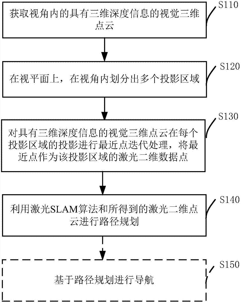
[0030] figure 1 It is a schematic flowchart of Example 1 of the path planning method for an intelligent robot according to the present invention. The intelligent robot is preferably a robot installed with a robot operating system. The method in this embodiment mainly includes the following steps.

[0031] In step S110, a visual three-dimensional point cloud with three-dimensional depth information within a viewing angle is acquired.

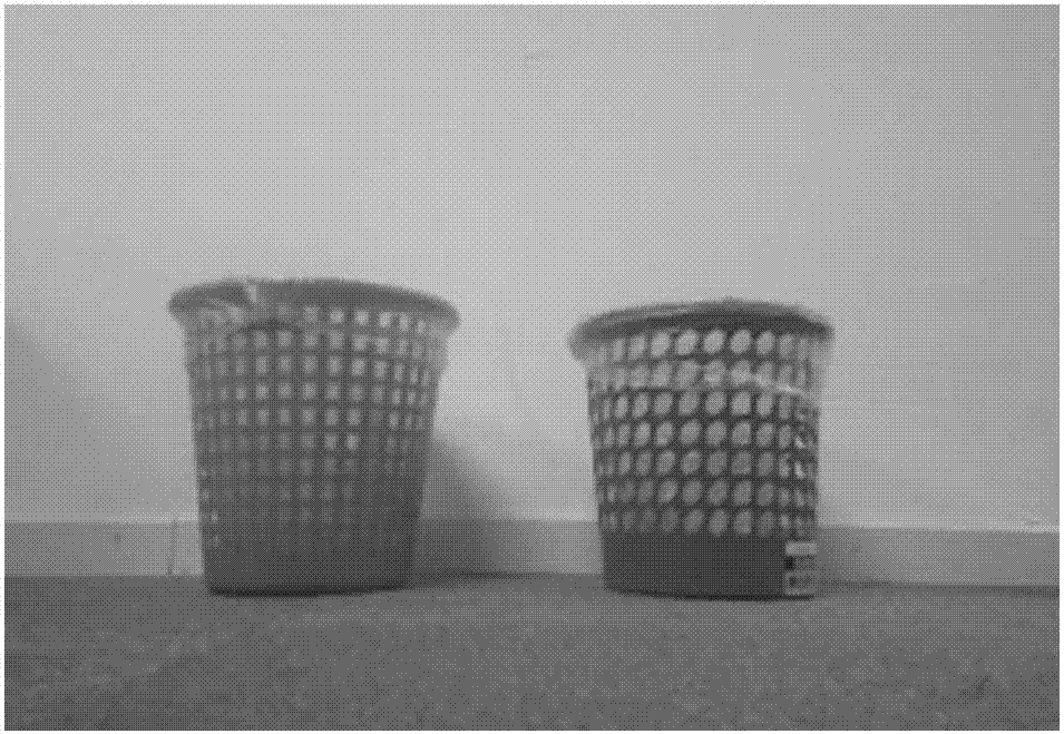
[0032] Specifically, the intelligent robot adopts a high-definition depth camera and uses structured light to perceive the scene in the viewing angle in real time (such as image 3 shown) and form a depth map image. Each pixel in the depth map image records the depth value of the scene, which is completely different from the light intensity value represented by the pixel in the ordinary RGB image. In addition, the depth camera can directly convert the collected depth map image into a visual 3D point cloud (such as Figure 4 As shown), it can a...

no. 2 example

[0044] Figure 6 It is a structural block diagram of a path planning device 600 for an intelligent robot according to an embodiment of the present application. Such as Figure 6 As shown, the path planning device 600 of the embodiment of the present application mainly includes: a visual 3D point cloud acquisition module 610 , a projection area division module 620 , a laser 2D point cloud acquisition module 630 , a path planning module 640 and a navigation module 650 .

[0045] A visual 3D point cloud acquisition module 610, which acquires a visual 3D point cloud with 3D depth information within a viewing angle. Further, the visual 3D point cloud acquisition module 610 also performs filtering and / or smoothing processing on the acquired visual 3D point cloud data to restore lost depth data.

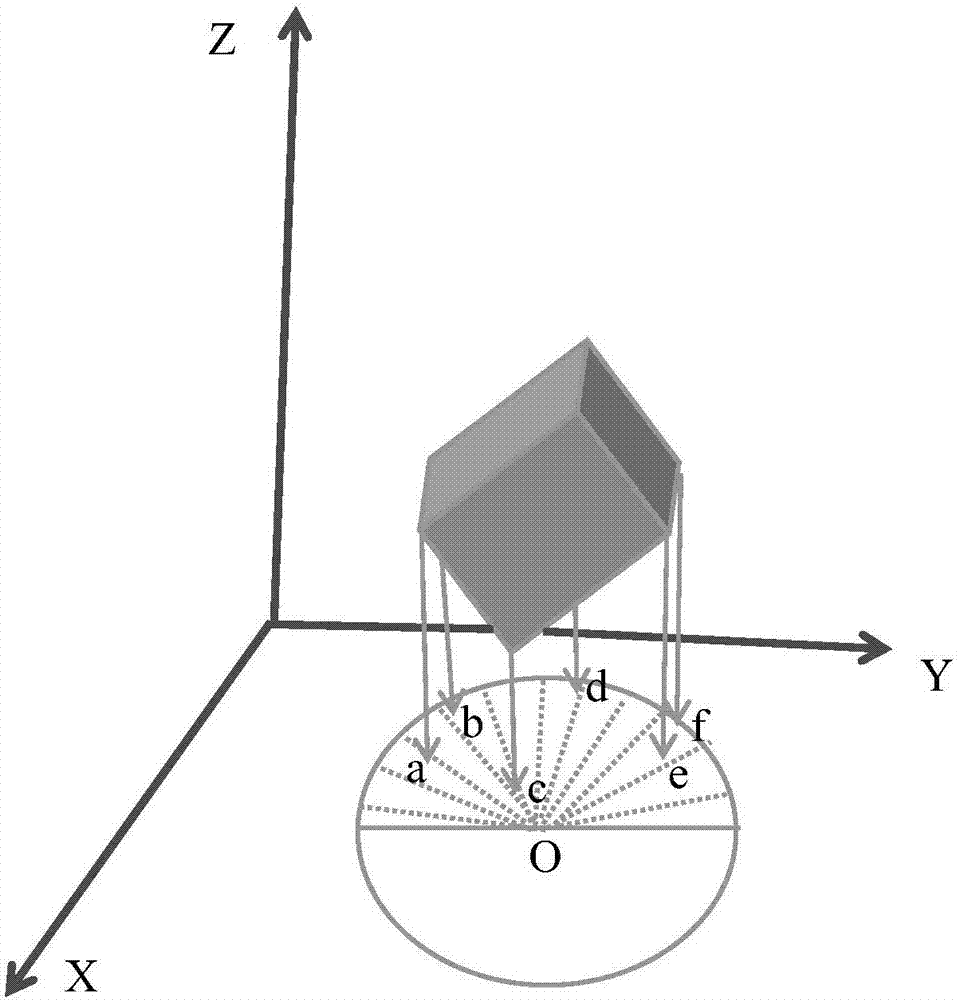
[0046] The projection area division module 620 divides a plurality of projection areas within the viewing angle on the viewing plane. The projection area division module 620 further divi...


PUM


Abstract

The invention discloses a route programming method for an intelligent robot. A robot operating system is mounted in the intelligent robot. The route programming method comprises the following steps: obtaining a vision three-dimensional point cloud with three-dimensional depth information in an angle of view; dividing the angle of view into a plurality of projection areas on a view plane; performing iterative closest point treatment on the projection of each projection area of the vision three-dimensional point cloud with the three-dimensional depth information, and using the closest point as a laser two-dimensional data point of the projection area, so as to obtain a laser two-dimensional point cloud corresponding to the vision three-dimensional point cloud; and utilizing a laser SLAM algorithm and the obtained laser two-dimensional point cloud to perform route programming. Through the adoption of the route programming method disclosed by the embodiment of the invention, the vision three-dimensional point cloud obtained through a depth vision camera is changed into the laser two-dimensional point cloud, and the laser SLAM algorithm and a vision sensor can be combined and used, so that the route programming and navigatation of the robot are completed, and the route programming stability of the robot using the vision sensor is effectively improved.

Description

technical field [0001] The invention relates to the field of intelligent robots, in particular to a path planning method and device for intelligent robots. Background technique [0002] With the rapid development of computers, sensors, control technology, artificial intelligence and other technologies, although robots have only experienced more than 50 years of development, as a new industry and technology under the traction of demand, robot technology has gained a lot of attention. Good development. Because there are many types of robots and different functions, they can be widely used in various fields such as industry and civil use. [0003] Simultaneous Localization and Mapping (SLAM for short) technology is a major development research direction in the field of robotics in recent decades. As the core technology of robots, SLAM technology has important research significance in robot navigation, control, production and other aspects. Generally speaking, SLAM technology...

Claims


Application Information

Patent Timeline
Patent Type & Authority Applications(China)
IPC IPC(8): G01C21/00
CPCG01C21/00
Inventor 代勇
Owner BEIJING GUANGNIAN WUXIAN SCI & TECH
Features
  • R&D
  • Intellectual Property
  • Life Sciences
  • Materials
  • Tech Scout
  • Unparalleled Data Quality
  • Higher Quality Content
  • 60% Fewer Hallucinations
Learn More