Automatic latex draining device and automatic latex draining method

An automatic rubber discharge and rubber discharge technology, which is applied in agriculture, forestry, application, etc., can solve the problems of large technical training costs, increased labor costs, and decreased rubber tapping quality, so as to ensure long-term benefits, save labor costs, and reduce the difficulty of rubber mining. Effect

Active Publication Date: 2017-07-04
RUBBER RES INST CHINESE ACADEMY OF TROPICAL AGRI SCI
View PDF8 Cites 8 Cited by
  • Summary
  • Abstract
  • Description
  • Claims
  • Application Information

AI Technical Summary

Problems solved by technology

[0007] Traditional manual tapping requires manual control of tapping depth and skin thickness, which requires high technical skills for workers, but it is very difficult after the rubber worker is tired, which may easily cause the quality of tapping to decline and cause damage to trees.
In addition, it takes a month or even longer to train a skilled rubber worker, and a lot of technical training costs have to be invested. In the current situation where the labor force is becoming increasingly tense, labor costs have increased significantly, and the rubber price market is not good, the production enterprises cannot make ends meet. It leads to the embarrassing situation that there is glue that cannot be cut, and there is no one to cut the glue, which causes greater losses to production.
[0008] Moreover, whether it is a manual rubber tapping knife or a mechanical rubber tapping knife, it is necessary to cut the bark of the rubber tree. After the collection is completed, the bark needs to be cut again for the next collection. Repeated cutting will damage the rubber tree, resulting in dead skin and no longer producing rubber. , affecting the production yield

Method used


Image

  • Automatic latex draining device and automatic latex draining method
  • Automatic latex draining device and automatic latex draining method
  • Automatic latex draining device and automatic latex draining method

Examples


Embodiment Construction

[0044] In order to enable those skilled in the art to better understand the technical solutions of the present invention, the present invention will be further described in detail below in conjunction with the accompanying drawings and specific embodiments.

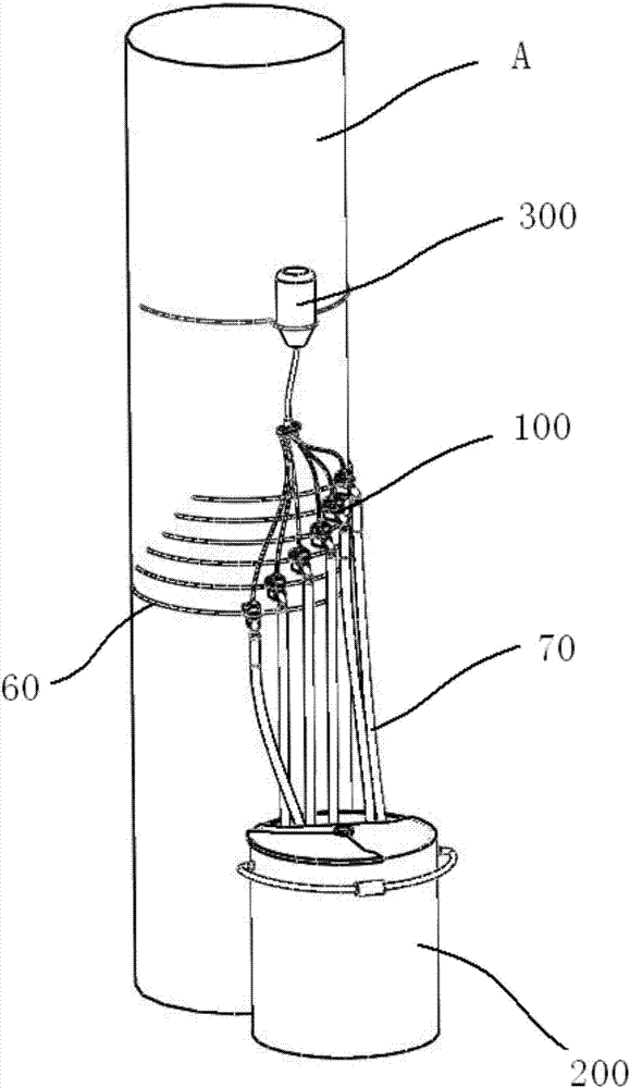
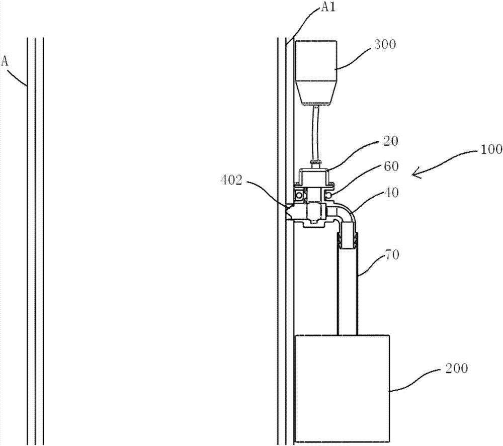
[0045] Please refer to figure 1 , figure 1 It is a structural schematic diagram of a specific embodiment of the automatic glue removal device provided by the present invention; figure 2 for figure 1 Vertical section view.

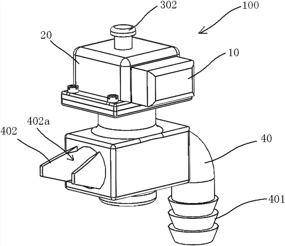
[0046] The automatic degumming device provided in this embodiment includes a degumming unit 100, and the degumming unit 100 includes a degumming pipe 40 and a latex anticoagulant, such as casein, polyacrylamide, etc., and the front end 402 of the degumming pipe 40 can Insert the rubber tree bark A to draw out the latex. That is, the position where the front end 402 of the rubber discharge pipe 40 is inserted is selected for the purpose of being able to draw out the latex, figure 2 Among them, th...


PUM


Abstract

The invention discloses an automatic latex draining device and an automatic latex draining method. The automatic latex draining device comprises a latex draining unit; the latex draining unit comprises a latex draining tube and an anticoagulation output part; an front end of the latex draining tube can be inserted in rubber tree barks to extract latex; the latex anticoagulation output by the anticoagulation output part can flow to a latex outlet in the rubber tree bark corresponding to the latex draining tube when latex extraction is stopped. According to the device and method of the invention, after the collection of latex is completed, the latex at the front end (which is inserted in the bark) of the latex draining tube is kept non-solidified and the latex draining tube is kept at the position for collecting latex; when latex is collected the next time, the latex in the rubber tree bark latex vessels can be directly collected through the latex at the front end of the latex draining tube to the latex draining tube without cutting again or inserting latex draining tubes again. Therefore, by means of the device and method, without repeatedly cutting tree barks, the difficulty of latex collecting is reduced and labor cost is saved. The more important thing is that the damage to rubber trees is reduced and long term benefit is guaranteed.

Description

technical field [0001] The invention relates to the technical field of rubber mining in the rubber industry, in particular to an automatic glue removal device and an automatic glue removal method. Background technique [0002] The rubber tree has an outer layer of gizzard skin, and the inner side of the gizzard skin is a water sac skin. There are a large number of milk ducts in the water sac skin. The milk ducts are natural latex synthesis organs. Natural rubber production is to collect latex in the latex tubes. At present, it mainly relies on manual rubber mining. The specific process is as follows: [0003] Manually operate a manual or electric rubber tapping knife to cut the bark of the rubber tree, and the cutting depth reaches at least the position of the above-mentioned water bladder skin to cut off the milk duct; often along the height direction of the trunk, cutting forms a spiral cutting line; [0004] A collection tank is set at the lowest point of the spiral cut...

Claims


Application Information

Patent Timeline
Patent Type & Authority Applications(China)
IPC IPC(8): A01G23/10
CPCA01G23/10Y02W30/62
Inventor 曹建华黄敞张以山郑勇吴思浩袁晓军
Owner RUBBER RES INST CHINESE ACADEMY OF TROPICAL AGRI SCI
Why Eureka
Try Eureka