

Hip joint replacement prosthesis
A hip replacement and prosthesis technology, applied in hip joints, prostheses, joint implants, etc., can solve the problems of uneven distribution of elastic modulus, self-weight, affecting functions, etc., achieve good structural mechanical properties, prevent The effect of sinking and rotating, enhancing the firmness of the connection
- Summary
- Abstract
- Description
- Claims
- Application Information
AI Technical Summary
Problems solved by technology
Method used
Image

Examples
Embodiment 1
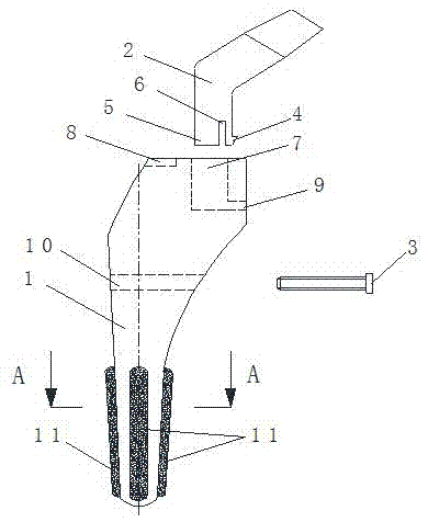
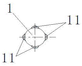
[0028] As attached to the manual Figure 1-2As shown, a hip joint replacement prosthesis includes a femoral stem 1, a femoral neck 2, and a fastening insert rod 3; The lower end of the neck 2 is composed of two parts, one of which is an elastic barb 4, and the other part is a columnar body 5, and an interval gap 6 is provided between the elastic barb 4 and the columnar body 5; An L-shaped through hole 7 is provided, and a positioning hole 8 is added to the upper end of the head of the femoral stem 1; the lower part of the femoral neck 2 is inserted into the L-shaped through hole 7, and the elastic barb 4 is hooked into the L-shaped through hole 7 in the transverse hole 9; the middle part of the femoral stem 1 is provided with a hole 10, the hole 10 is interference-fitted with a fastening rod 3; the lower surface of the femoral stem 1 is attached with The convex ribs 11 are four uniformly distributed along the axial direction of the femoral stem 1; in this embodiment, the mult...
Embodiment 2
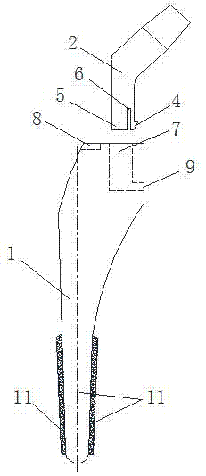
[0040] As attached to the manual image 3 As shown, a hip joint replacement prosthesis includes a femoral stem 1 and a femoral neck 2; the lower part of the femoral neck 2 is in the shape of a positive column as a whole, and the upper part is set as an offset inclined column; the lower end of the femoral neck 2 is formed by It consists of two parts, one part is elastic barb 4, the other part is columnar body 5, and there is a gap 6 between elastic barb 4 and columnar body 5; the head of femoral stem 1 is provided with L-shaped through hole 7, and the upper end of the head of the femoral stem 1 is provided with a positioning hole 8; the lower part of the femoral neck 2 is inserted into the L-shaped through hole 7, and the elastic barb 4 is hooked into the transverse hole 9 on the L-shaped through hole 7 Inside; the outer surface of the lower part of the femoral stem 1 is attached with ribs 11 made of multi-level porous material, and the ribs 11 are two evenly distributed along ...
Embodiment 3
[0051] As attached to the manual Figure 4 As shown, a hip joint replacement prosthesis includes a femoral stem 1 and a femoral neck 2; the lower part of the femoral neck 2 is in the shape of a positive column as a whole, and the upper part is set as an offset inclined column; the lower end of the femoral neck 2 is formed by It consists of two parts, one part is elastic barb 4, the other part is columnar body 5, and there is a gap 6 between elastic barb 4 and columnar body 5; the head of femoral stem 1 is provided with L-shaped through hole 7. The lower part of the femoral neck 2 is inserted into the L-shaped through hole 7, and the elastic barb 4 is hooked into the transverse hole 9 on the L-shaped through hole 7; the lower part of the femoral stem 1 is attached with a multi-level hole The convex ribs 11 made of material, the ribs 11 are four uniformly distributed along the axial direction of the femoral stem 1 ;
[0052] According to the actual situation of different patien...
PUM
| Property | Measurement | Unit |
|---|---|---|
| Particle size | aaaaa | aaaaa |
| Particle size | aaaaa | aaaaa |
| Particle size | aaaaa | aaaaa |
Abstract
Description
Claims
Application Information