A Cushioned Hip

A hip joint and hole cavity technology, applied in hip joints, joint implants, joint implants, etc., can solve problems such as uneven mechanical strength, elastic modulus, impact on function, hidden quality problems, etc., and achieve good structural mechanics. performance, slowing down severe impact, avoiding the effect of failure and waste

Active Publication Date: 2019-02-19
CHONGQING RUNZE PHARM CO LTD
View PDF6 Cites 0 Cited by
  • Summary
  • Abstract
  • Description
  • Claims
  • Application Information

AI Technical Summary

Problems solved by technology

[0004] However, most of the porous structures used in artificial joint replacement prostheses are single-pore materials, and the reports on the selection of multi-level porous materials are very limited.
This may be mainly due to the fact that the existing porous materials themselves have a significant decrease in structural mechanical strength with the increase of porosity, so the porosity is generally low and the permeability is low, which is not conducive to the efficient exchange of substances in human tissues. Poor biocompatibility, heavy weight, and poor postoperative human experience; in addition, in order to apply to bionic artificial bones, the material itself needs to be uniform, that is, the size of the pores and the distribution of the pores are uniform, so that the performance is uniform, but in fact, There are many hierarchical porous materials that cannot meet this requirement, and their uniformity is insufficient; although some materials claim to have achieved high uniformity, their uniformity is still the uniformity at the large volume scale. To measure and compare, for example, take a number of three-dimensional bodies whose volume is not larger than one cubic centimeter on the material, and measure their masses respectively. The difference in the degree of inhomogeneity is still very large, which leads to inhomogeneity in various properties of the multi-level porous material, such as the size of the pores. , Uneven distribution of voids leads to uneven distribution of mechanical strength, elastic modulus, etc., resulting in defects such as hidden quality, which seriously affects its function
For example, CN201210185031 discloses a preparation method of a bionic artificial bone with a multi-level (micron / nanometer) pore structure, but the three-dimensional multi-level pore structure obtained by this method still cannot meet the requirements due to the randomness and irregularity of the pore structure. Functional requirements of bionic artificial bone

Method used


Image

  • A Cushioned Hip
  • A Cushioned Hip
  • A Cushioned Hip

Examples


Embodiment 1

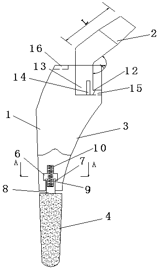
[0031] As attached to the manual Figure 1-3As shown, a cushioning hip joint includes a femoral stem 1, a femoral neck 2 and a spring 10; its femoral stem 1 is split into two parts, the proximal end 3 and the distal end 4; the head of the proximal end 3 is provided with L-shaped through hole 5, and the head of proximal end 3 is provided with positioning hole 16; One part is a barb 12, the other part is a columnar body 13, and a gap 14 is provided between the barb 12 and the columnar body 13; the lower part of the femoral neck 2 is inserted into the L-shaped through hole 5, and the barb 12 is hooked in the transverse hole 15 on the L-shaped through hole 5; the lower part of the proximal end of the femoral stem 1 is provided with an inner hole 6, and the middle cavity of the inner hole 6 is a cylinder, and the inner diameter of the middle cavity is larger than the inner diameter. The maximum inner diameter of the upper and lower cavities of the hole 6, the end of the cylindrica...

Embodiment 2

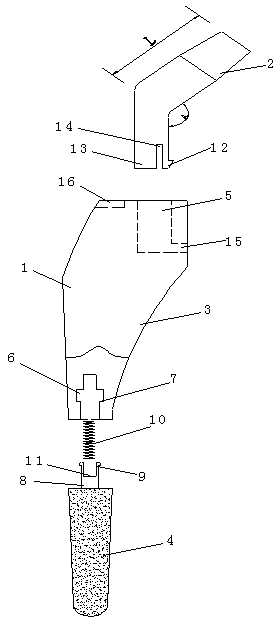
[0043] As attached to the manual Figure 4-5 As shown, a cushioning hip joint includes a femoral stem 1, a femoral neck 2 and a spring 10; its femoral stem 1 is split into two parts, the proximal end 3 and the distal end 4; the head of the proximal end 3 is provided with L-shaped through hole 5; the lower part of the femoral neck 2 is in the shape of a positive column as a whole, and the upper part is set as an offset inclined column; the lower end of the femoral neck 2 is composed of two parts, one part of which is a barb 12, and the other part is a columnar body 13, and a gap 14 is provided between the barb 12 and the columnar body 13; the lower part of the femoral neck 2 is inserted into the L-shaped through hole 5, and the barb 12 is hooked into the transverse hole 15 on the L-shaped through hole 5 Inside; the lower part of the proximal end of the femoral stem 1 is provided with an inner hole 6, and two symmetrically distributed discontinuous stepped surfaces 7 are arrange...

Embodiment 3

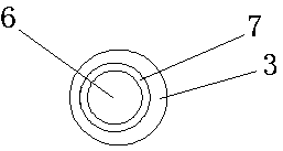
[0054] As attached to the manual Image 6 As shown, a cushioning hip joint includes a femoral stem 1 and a femoral neck 2; the femoral stem 1 is split into two parts, the proximal end 3 and the distal end 4; the head of the proximal end 3 is provided with an L-shaped through hole 5; the lower part of the femoral neck 2 is in the shape of a positive column as a whole, and the upper part is set as an offset inclined column; the lower part of the femoral neck 2 is inserted into the L-shaped through hole 5 through interference fit; the proximal end of the femoral stem 1 The lower part is provided with an inner hole 6, which is provided with a continuous annular stepped surface 7; its distal end 4 is made of a multi-stage porous material, and a connecting rod 8 is added on the head of the distal end 4, and the connecting rod 8 is connected The end of the rod 8 has an elastic barb 9; the connecting rod 8 is inserted into the inner hole 6, and the elastic barb 9 is hooked at the step...


PUM


Abstract

The invention relates to a buffer hip joint. The hip joint comprises a femoral stem (1) and a femoral neck (2). The hip joint is characterized in that the femoral stem (1) is divided in two parts of a near end (3) and a far end (4). The heat of the near end (3) is internally provided with an L-shaped hole (5). The lower part of the femoral neck (2) is plugged in the L-shaped hole (5). The lower part of the near end (3) is provided with an inner hole (6), and the inner hole (6) is internally provided with a step surface (7). The far end (4) is made of a hierarchical porous material. The head of the far end (4) is added with a connecting rod (8). The end of the connecting rod (8) is provided with an elastic barb (9). The connecting rod (8) is plugged in the inner hole (6), and the elastic barb (9) is hooked and clamped in the step surface (7) of the inner hole (6). The inner hole (6) is longer than the connecting rod (8). The hip joint is reasonable in structural design, and connection stability and biocompatibility are relatively high, and post-surgery healing effect is better and faster.

Description

technical field [0001] The invention relates to human body joint replacement, in particular to a cushioning hip joint. Background technique [0002] At present, most of the existing artificial hip replacement prostheses are designed in one piece. Although it has the advantages of being easy to process and shape, if some parts break, such as neck breaks, it will lead to the failure of the overall function of the structure. Undoubtedly, it caused huge waste; at the same time, because the one-piece design itself has the defect of lacking a buffer function, it suffers poorly from alternating force and has a short service life in application. In addition, the replacement prosthesis of the existing design still has low stability of connection with human tissue, easy to loosen, rotate and fall off; poor biocompatibility, easy to suffer rejection after implantation, poor postoperative healing effect, etc. common problem. It is difficult to realize all these problems by simply rely...

Claims


Application Information

Patent Timeline
Patent Type & Authority Patents(China)
IPC IPC(8): A61F2/32A61F2/36
CPCA61F2/32A61F2/3601A61F2/3607A61F2/3609A61F2002/3611
Inventor 叶雷
Owner CHONGQING RUNZE PHARM CO LTD
Why Eureka
Try Eureka