Ejection type glider model

A glider and catapult technology, applied in toy planes, entertainment, toys, etc., can solve the problems of inability to leave automatically, prolong the empty time of the plane, achieve precise processing and control, increase the empty time, and improve the lift-to-drag ratio. Effect

Inactive Publication Date: 2017-07-04
TIANJIN NORMAL UNIVERSITY
View PDF6 Cites 0 Cited by
  • Summary
  • Abstract
  • Description
  • Claims
  • Application Information

AI Technical Summary

Problems solved by technology

The traditional catapult glider cannot automatically enter when encountering an updraft, and cannot automatically leave when encountering a downdraft, which is not conducive to prolonging the flight time of the aircraft

Method used


Image

  • Ejection type glider model
  • Ejection type glider model
  • Ejection type glider model

Examples


Embodiment Construction

[0034] The technical solution of the present invention will be further described below in conjunction with the accompanying drawings.

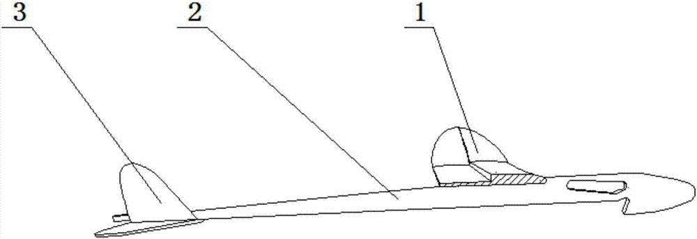
[0035] Such as Figure 1-11 Shown, comprise: fuselage 2 and the wing 1 (wing level installation) that is installed on the fuselage and empennage 3, form the through hole that is used to adjust the center of gravity of catapult glider model in the front part of fuselage (not in the figure shown) and a hook for ejection (not shown).

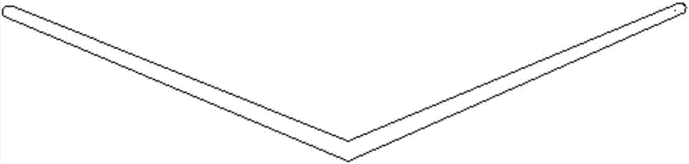
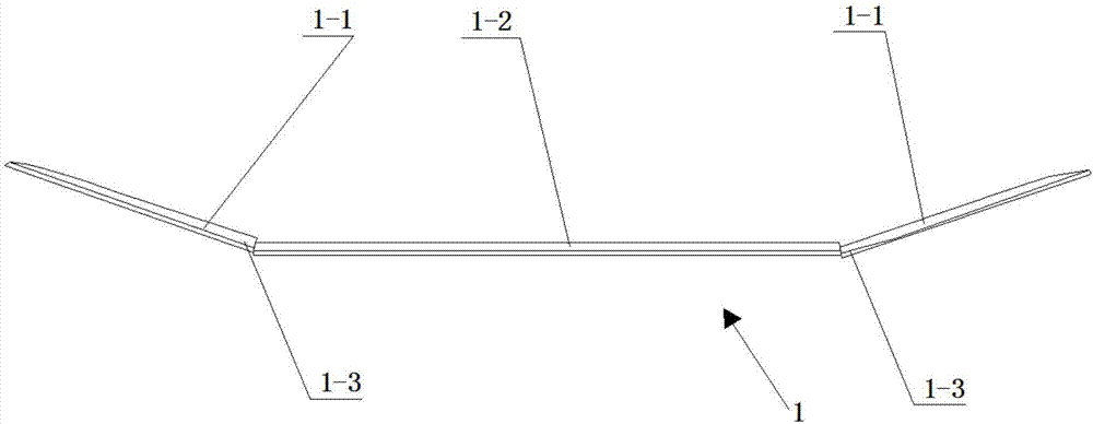
[0036] The dihedral of the traditional aircraft adopts a two-stage one-fold wing, such as figure 1 As shown, the assembly accuracy of this kind of wing is not easy to improve, it is easy to install crookedly, and the assembly is difficult. In the present invention, the wing is installed in three sections, and the wing is made up of the middle section 1-2 of the wing and 2 wingtips 1-1, as figure 2 As shown, the middle section of the wing is installed on the fuselage through a mortise and tenon mechanism, which ...


PUM


Abstract

The invention discloses an ejection type glider model comprising a glider body, a wing and an empennage mounted on the glider body. The wing is formed by a wing middle section and two wing tips; the two wing tips are respectively fixed on two ends of the wing middle section; an anhedral of each wing tip is 15 to 25 degrees; the back edge of the wing tip on the left end of the wing middle section is 0.8 to 1mm upwardly staggered in a vertical direction; the back edge of the wing tip on the right end of the wing middle section is 0.8 to 1mm downwardly staggered in the vertical direction; the upper surface of the wing forms a step bench along a length direction of the wing; the empennage is formed by a first empennage and a vertical second empennage; the first empennage is installed on the glider body in a way of forming a rotation angle of 2-3 DEG by taking the glider body as a center shaft and the horizontal plane as a starting point; the lower end of the second empennage is fixed on the upper surface of the first empennage; and the side surface of the second empennage is fixed on the glider body. The wing tip staggered installation provides a stable rising path when the ejection glider model vertically rises; and the climbing height can surpass 30 meters.

Description

technical field [0001] The invention belongs to the technical field of aircraft for scientific and technological activities, and in particular relates to a catapult glider model. Background technique [0002] Catapult models have a long history as toys or as teaching aids for beginners in aviation. The traditional catapult glider cannot automatically enter when encountering an updraft, and cannot automatically leave when encountering a downdraft, which is not conducive to prolonging the flight time of the aircraft. Contents of the invention [0003] In view of the deficiencies in the prior art, the purpose of the present invention is to provide a catapult glider model, which can automatically enter the updraft and automatically leave the downdraft. [0004] The purpose of the present invention is achieved through the following technical solutions. [0005] A catapult glider model, comprising: a fuselage and a wing and an empennage mounted on the fuselage; At both ends o...

Claims


Application Information

Patent Timeline
Patent Type & Authority Applications(China)
IPC IPC(8): A63H27/18A63H27/22A63H29/18
CPCA63H27/02A63H29/18
Inventor 郭树冠赵一航
Owner TIANJIN NORMAL UNIVERSITY
Why Eureka
Try Eureka