Multistage driving type material stirring mechanism

A stirring mechanism and driven technology, which is applied in the field of multi-stage driven material stirring mechanism, can solve the problems of insufficient material processing, affecting work efficiency, uneven stirring, etc., achieve high-speed, high-efficiency, high-stability solution stirring, improve production efficiency, The effect of improving homogeneity

Pending Publication Date: 2017-07-04
ANHUI JINLONG MACHINERY
View PDF7 Cites 4 Cited by
  • Summary
  • Abstract
  • Description
  • Claims
  • Application Information

AI Technical Summary

Problems solved by technology

[0002] The evaporator is a very important part of the four major components of refrigeration. The low-temperature condensed "liquid" body passes through the evaporator to exchange heat with the outside air, and the "gas" absorbs heat to achieve the effect of refrigeration. The evaporator is currently It is used in various large-scale chemical enterprises. The main components will be used to stir and mix different materials before collecting or using the solution. Therefore, in the whole system, the stirring tank is one of the indispensable devices, and due to evaporation Crystallization has strict requirements for solution concentration. Therefore, when using traditional stirring devices, the stirring speed is slow and the stirring is not uniform enough, which can easily cause insufficient thorough material processing, high waste rate of raw materials, and affect the overall work efficiency.

Method used


Image

  • Multistage driving type material stirring mechanism
  • Multistage driving type material stirring mechanism
  • Multistage driving type material stirring mechanism

Examples


Embodiment 1

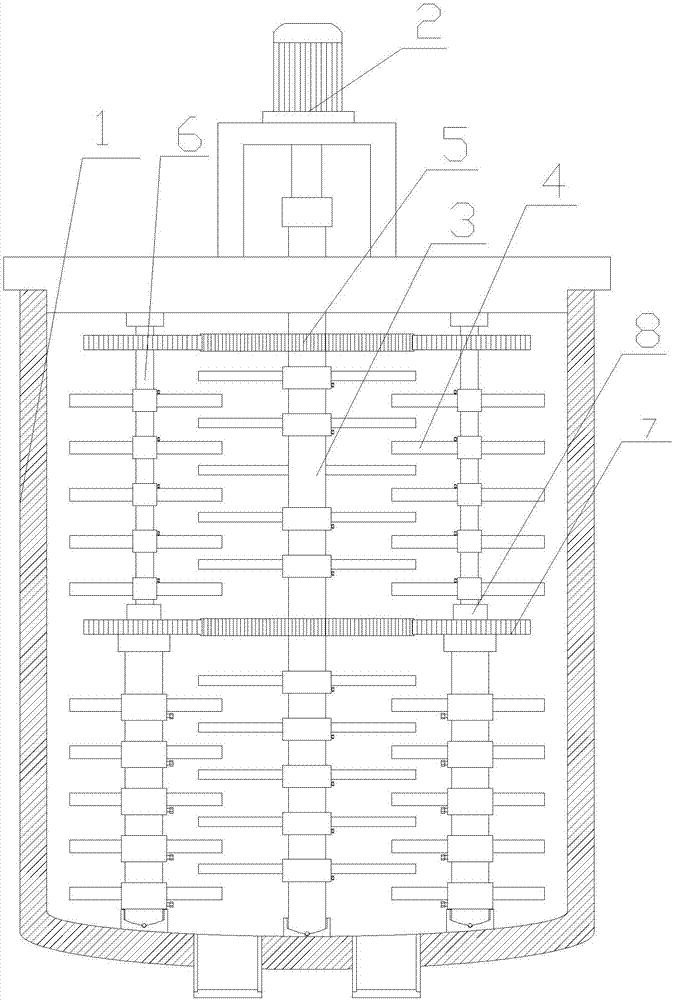
[0018] Such as figure 1 , figure 2 As shown, a multi-stage drive type material mixing mechanism, the main body includes a mixing tank 1, a driving motor 2 on the top of the mixing tank 1, a middle driving shaft 3 located inside the mixing tank 1, and a middle driving shaft 3 The upper mixing blade 4, the top of the middle drive shaft 3 passes through the mixing tank 1 and is connected to the drive motor 2 shaft, the middle drive shaft 3 is installed with a driving drive gear 5, and the two ends of the middle drive shaft 3 are installed with side drive shafts 6. A driven drive gear 7 is installed on the side drive shaft 6, the active drive gear 5 is toothed with the driven drive gear 7, and the side drive shaft 6 is installed with mixing blades 4 staggered with the middle drive shaft 3. , While the drive motor 2 drives the middle drive shaft 3 to stir, the active drive gear 5 on the middle drive shaft 3 drives the driven drive gear 7 on the side drive shaft 6 to drive the side d...

Embodiment 2

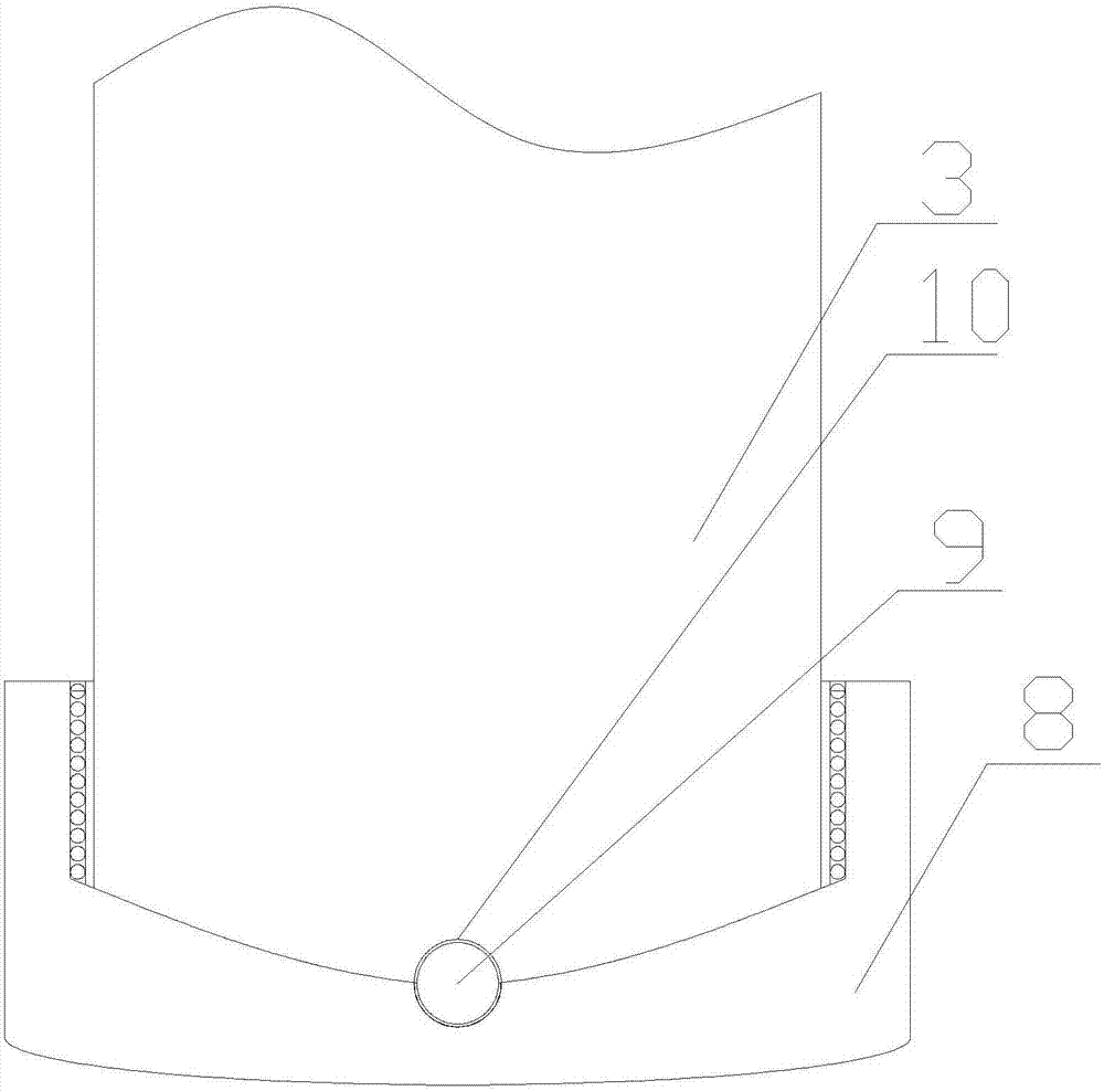
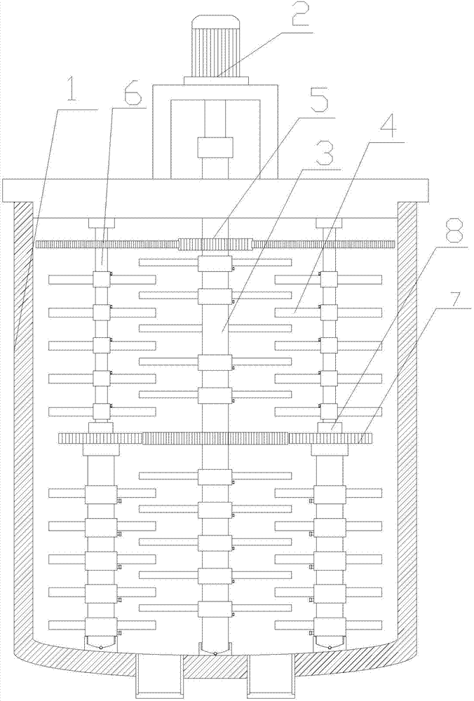
[0020] Such as figure 2 , image 3 As shown, a multi-stage drive type material mixing mechanism, the main body includes a mixing tank 1, a driving motor 2 on the top of the mixing tank 1, a middle driving shaft 3 located inside the mixing tank 1, and a middle driving shaft 3 The upper mixing blade 4, the top of the middle drive shaft 3 passes through the mixing tank 1 and is connected to the drive motor 2 shaft, the middle drive shaft 3 is installed with a driving drive gear 5, and the two ends of the middle drive shaft 3 are installed with side drive shafts 6. A driven drive gear 7 is installed on the side drive shaft 6, the active drive gear 5 is toothed with the driven drive gear 7, and the side drive shaft 6 is installed with mixing blades 4 staggered with the middle drive shaft 3. , While the drive motor 2 drives the middle drive shaft 3 to stir, the active drive gear 5 on the middle drive shaft 3 drives the driven drive gear 7 on the side drive shaft 6 to drive the side ...


PUM


Abstract

A multistage driving type material stirring mechanism comprises a stirring tank, a driving motor arranged on the top of the stirring tank, a middle driving shaft arranged in the stirring tank, and stirring blades arranged on the middle driving shaft. The top of the middle driving shaft penetrates the stirring tank and is connected to the shaft of the driving motor. Active driving gears are arranged on the middle driving shaft. Two ends of the middle driving shaft are both provided with a lateral driving shaft. Inactive driving gears are arranged on the lateral driving shafts. The active driving gears and the inactive driving gears are engaged with each other. The lateral driving shafts are provided with stirring blades, which axially intersect with the middle driving shaft. The structure is simple, the design is novel, a set of driving motor can drive multiple mechanisms to work at the same time, a solution can be stirred efficiently and stably at a high speed, the solution uniformity in evaporation and crystallization is guaranteed, the production efficiency is improved, the energy consumption is low, and the design cost is low.

Description

Technical field [0001] The invention relates to the technical field of stirring device manufacturing, in particular to a multi-stage drive type material stirring mechanism. Background technique [0002] The evaporator is a very important part of the four major components of refrigeration. The low-temperature condensed "liquid" body passes through the evaporator to exchange heat with the outside air, "gas" and absorb heat to achieve the effect of cooling. The evaporator is at this stage It is used in various large-scale chemical enterprises. The main components will be used for different materials to be collected or mixed before the solution is mixed. Therefore, in the entire system, the stirring tank is one of the indispensable devices, and due to evaporation Crystallization has more stringent requirements for solution concentration. Therefore, using traditional stirring devices, the stirring rate is slow and the stirring is not even enough, which can easily cause insufficient pr...

Claims


Application Information

Patent Timeline
Patent Type & Authority Applications(China)
IPC IPC(8): B01F7/18B01D1/00
CPCB01D1/00B01F27/074B01F27/2121B01F27/112B01F27/2711B01F27/421B01F27/2322B01F27/90
Inventor 张向阳凡晓峰张正坦
Owner ANHUI JINLONG MACHINERY
Why Eureka
Try Eureka