Industrial control ultrasonic probe and method for improving industrial control ultrasonic probe

An industrial control, single-layer technology, applied in the field of ultrasonic probes, can solve problems such as low sensitivity and unsatisfactory sensitivity, and achieve the effects of improving sensitivity, increasing sensitivity and reliable adjustment.

Active Publication Date: 2017-07-04
江苏波速传感器有限公司
View PDF5 Cites 0 Cited by
  • Summary
  • Abstract
  • Description
  • Claims
  • Application Information

AI Technical Summary

Problems solved by technology

[0002] With the vigorous development of the robot industry, the demand for industrial control ultrasonic probes is increasing, and the sensitivity requirements for the probes are also getting higher and higher. It is: ① Start with the material of the ultrasonic probe to reduce the sound attenuation of the probe; ② Adjust the frequency of the ultrasonic probe; ③ Match between the ultrasonic probe and the circuit, etc. After using these methods, the sensitivity of the ultrasonic probe can be improved to a certain extent, but its sensitivity It still cannot meet the requirements of its application in the robot industry. Therefore, the problem of how to improve the sensitivity of the ultrasonic probe needs to be solved urgently.

Method used


Image

  • Industrial control ultrasonic probe and method for improving industrial control ultrasonic probe
  • Industrial control ultrasonic probe and method for improving industrial control ultrasonic probe
  • Industrial control ultrasonic probe and method for improving industrial control ultrasonic probe

Examples


Embodiment 1

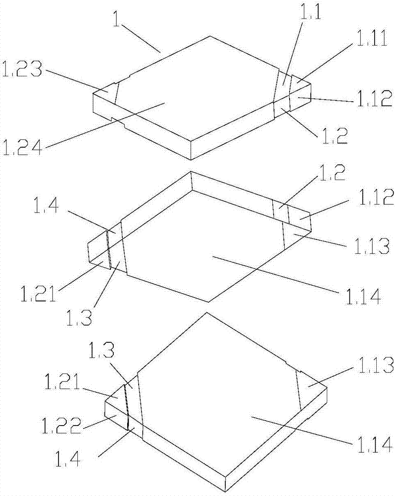
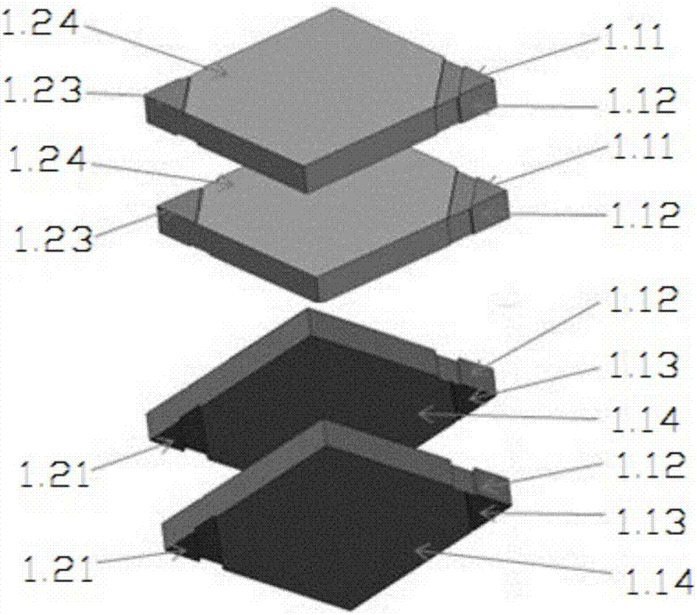
[0022] Embodiment 1: Piezoelectric ceramic sheet, with reference to Figure 1 to Figure 3 As shown, it consists of two single-layer ceramic sheets 1 stacked up and down. A downward frontal groove 1.1 is provided at a corner of the front side of the single-layer ceramic sheet 1. The two sides of the corner form a concave positive side groove 1.2, and the positive groove 1.1 and the positive side groove 1.2 have the same concave depth and width, and the positive groove 1.1 and the positive side groove 1.2 divide the corner into a single layer In the first electrode area of ​​the ceramic sheet 1, the upward surface of the first electrode area is the first positive electrode surface 1.11, the downward surface of the first electrode area is the third positive electrode surface 1.13, and the left side of the first electrode area is the first positive electrode surface 1.11. The two positive electrode surfaces 1.12, the first positive electrode surface 1.11, the second positive elect...

Embodiment 2

[0025]Embodiment 2: piezoelectric ceramic sheet, with reference to Figure 1 to Figure 3 As shown, it is composed of four single-layer ceramic sheets 1 stacked up and down. A downward frontal groove 1.1 is provided at a corner of the front side of the single-layer ceramic sheet 1, and the two ends of the frontal groove 1.1 extend to the two sides of the corner and are on the corner. The two sides of the corner form a concave positive side groove 1.2, and the positive groove 1.1 and the positive side groove 1.2 have the same concave depth and width, and the positive groove 1.1 and the positive side groove 1.2 divide the corner into a single layer In the first electrode area of ​​the ceramic sheet 1, the upward surface of the first electrode area is the first positive electrode surface 1.11, the downward surface of the first electrode area is the third positive electrode surface 1.13, and the left side of the first electrode area is the first positive electrode surface 1.11. The...


PUM


Abstract

The invention belongs to the technical field of ultrasonic probes and particularly relates to an industrial control ultrasonic probe and a method for improving the industrial control ultrasonic probe. The industrial control ultrasonic probe comprises a matching layer, a metal shell, a positive electrode PIN, a negative electrode PIN, a PCB and a piezoelectric ceramic piece; the piezoelectric ceramic piece is composed in the manner that a plurality of single-layer ceramic piece bodies are stacked in an up-down manner; motor areas of the plurality of single-layer ceramic piece bodies are correspondingly conducted; the bottom end of the metal shell and the matching layer are glued; the piezoelectric ceramic piece is glued to the portion, corresponding to the interior of the metal shell, of the matching layer; the inner side of the upper end of the metal shell is of a step structure; the PCB is glued to the position of the step structure of the metal shell; the positive electrode of the piezoelectric ceramic piece is connected with the positive electrode of the PCB through a positive electrode line; the negative electrode of the piezoelectric ceramic piece is connected with the negative electrode of the PCB through a negative electrode line; the positive electrode PIN is connected with the positive electrode of the PCB in a riveted manner; the negative electrode PIN is connected with the negative electrode of the PCB in a riveted manner; and the top end of the metal shell is sealed through silica gel, and the sensitivity of the industrial control ultrasonic probe is substantially improved.

Description

technical field [0001] The invention belongs to the technical field of ultrasonic probes, and in particular relates to an industrial control ultrasonic probe and a method for improving the industrial control ultrasonic probe. Background technique [0002] With the vigorous development of the robot industry, the demand for industrial control ultrasonic probes is increasing, and the sensitivity requirements for the probes are also getting higher and higher. It is: ① Start with the material of the ultrasonic probe to reduce the sound attenuation of the probe; ② Adjust the frequency of the ultrasonic probe; ③ Match between the ultrasonic probe and the circuit, etc. After using these methods, the sensitivity of the ultrasonic probe can be improved to a certain extent, but its sensitivity It still cannot meet the requirements of its application in the robot industry. Therefore, the problem of how to improve the sensitivity of the ultrasonic probe needs to be solved urgently. Con...

Claims


Application Information

Patent Timeline
Patent Type & Authority Applications(China)
IPC IPC(8): B06B1/06
CPCB06B1/0696
Inventor 龙阳
Owner 江苏波速传感器有限公司
Why Eureka
Try Eureka