
Pneumatic hammer

A pneumatic hammer and motion technology, used in metal processing equipment, metal processing, manufacturing tools, etc., can solve the problems of high frequency of replacement parts, low production efficiency, increased cost, etc., and achieve reliable equipment operation, high production efficiency, and failure. low rate effect

Pending Publication Date: 2017-07-04
YUDO SUZHOU HOT RUNNER SYST
View PDF6 Cites 0 Cited by
  • Summary
  • Abstract
  • Description
  • Claims
  • Application Information

AI Technical Summary

Problems solved by technology

[0002] In the existing technology, the stamping heating wire in the manifold is realized by manual crimping or ordinary air hammer. Due to the high frequency of action, the ordinary air hammer needs to replace the spring frequently, which is time-consuming and low in work efficiency; therefore, a This kind of device or tool can do reciprocating stamping under the condition of high frequency and long time without the need of spring, stamping the heating wire into the splitter plate and compressing the heating wire
[0003] In the process of stamping the heating wire, the frequency of the impact speed is not high. When the stamping force is small and the high frequency works for a long time, the parts such as springs are easily fatigued and damaged. Therefore, the frequency of replacing parts is high and the cost increases. At the same time, it takes a long time to replace parts, resulting in low production efficiency. high

Method used


Image

  • Pneumatic hammer
  • Pneumatic hammer
  • Pneumatic hammer

Examples


Embodiment Construction

[0021] In order to make the object, technical solution and advantages of the present invention clearer, the specific implementation manners of the present invention will be described in detail below in conjunction with the accompanying drawings. Examples of these preferred embodiments are illustrated in the accompanying drawings. The embodiments of the invention shown in and described with reference to the drawings are merely exemplary, and the invention is not limited to these embodiments.

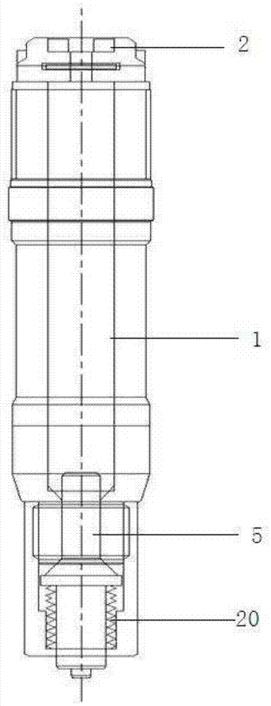
[0022] Such as figure 1 As shown, it is a schematic diagram of a pneumatic hammer in the prior art. In the prior art, the pneumatic punch 5 is driven by the air intake to drive the punch, and the spring 20 provides buffer and drives the moving punch to return and reciprocate. Due to the high frequency of action, the spring is easily damaged , resulting in low production efficiency, small impact and small adjustable range.

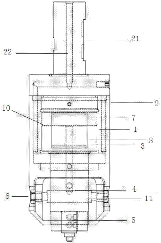
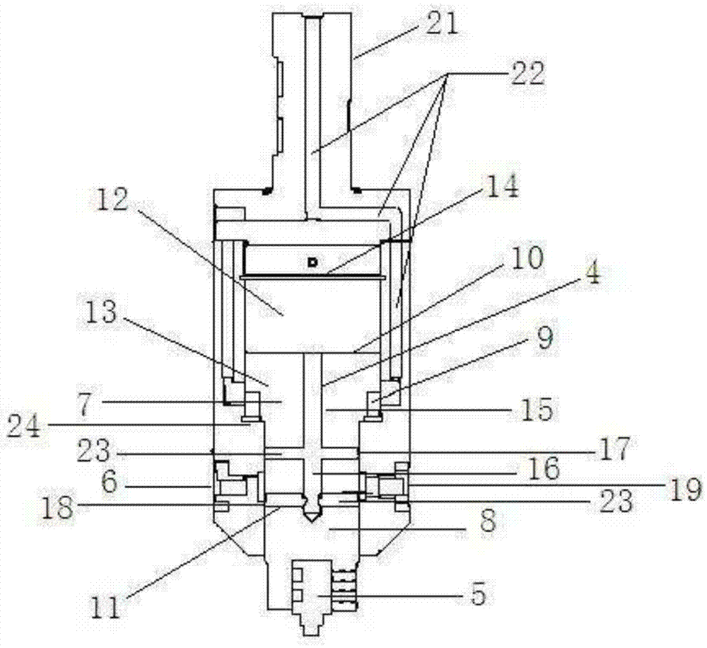
[0023] Such as figure 2 , image 3 As shown, the pneumatic h...


PUM


Abstract

The invention discloses a pneumatic hammer. The pneumatic hammer comprises a body, a shell body arranged outside the body, a cavity body formed in the body, a movable punch arranged in the cavity body, a pneumatic punch pin arranged at the bottom of the body, an air inlet pipeline and air outlets, wherein the air inlet pipeline and the air outlets communicate with the cavity body, the cavity body is divided into an upper cavity body and a lower cavity body, the area of the cross section of the upper cavity body is larger than that of the cross section of the lower cavity body, and step-shaped bosses are formed at the joint of the upper cavity body and the lower cavity body; air inlets of the air inlet pipeline communicate with the upper cavity body, and the air outlets communicate with the lower cavity body; and the movable punch comprises a top piston and a bottom piston, an upper cylinder body which is relatively sealed is formed between the top piston and the top of the shell body, and a lower cylinder body which is relatively sealed is formed between the bottom piston and the top of the movable punch. The pneumatic hammer can do reciprocating stamping motion under long-time and high-frequency working conditions without a spring, and the pneumatic hammer is high in punching pressure, low in work failure rate under the long-time and high-frequency working conditions, and high in production efficiency.

Description

technical field [0001] The invention relates to technical fields such as system injection molding equipment, hot runner systems, injection mold industry, numerical control machine tool industry, etc., and specifically relates to a pneumatic hammer for stamping heating wire devices or tools in a manifold. Background technique [0002] In the existing technology, the stamping heating wire in the manifold is realized by manual crimping or ordinary air hammer. Due to the high frequency of action, the ordinary air hammer needs to replace the spring frequently, which is time-consuming and low in work efficiency; therefore, a This kind of device or tool can do reciprocating stamping under the condition of high frequency and long time without spring, stamping the heating wire into the splitter plate and can compress the heating wire. [0003] In the process of stamping the heating wire, the frequency of the impact speed is not high. When the stamping force is small and the high freq...

Claims


Application Information

Patent Timeline
IPC IPC(8): B23P19/027
CPCB23P19/027
Inventor 李象烈
Owner YUDO SUZHOU HOT RUNNER SYST
Learn More