Device and method for increasing FPGA prototype verification efficiency

A prototype verification and efficiency technology, applied in CAD circuit design, special data processing applications, instruments, etc., can solve problems such as difficult positioning, wide verification process, and high complexity of chip design, and achieve the effect of improving verification efficiency

Active Publication Date: 2017-07-04
INSPUR SUZHOU INTELLIGENT TECH CO LTD
View PDF3 Cites 3 Cited by
  • Summary
  • Abstract
  • Description
  • Claims
  • Application Information

AI Technical Summary

Problems solved by technology

However, due to the complexity of chip design is often relatively large, the verification process is more complicated and involves a wider range of problems, and it will be more difficult to locate problems when they occur.

Method used


Image

  • Device and method for increasing FPGA prototype verification efficiency
  • Device and method for increasing FPGA prototype verification efficiency

Examples


Embodiment 1

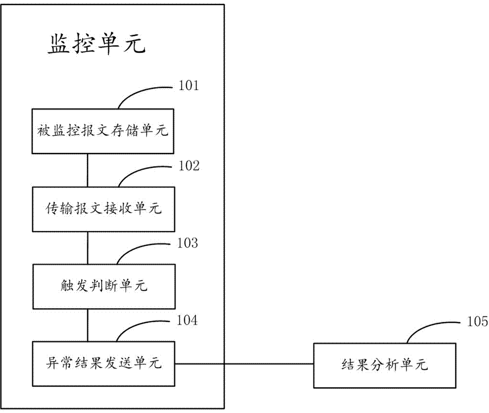
[0028] Please refer to figure 1 , A device for improving the efficiency of FPGA prototype verification, the device comprising: a monitoring unit, the monitoring unit further comprising: a monitored message storage unit 101, a transmission message receiving unit 102, a trigger judgment unit 103, and an abnormal result sending unit 104 ,among them:

[0029] The monitored message storage unit 101 is used to store the content of the monitored message;

[0030] The transmission message receiving unit 102 is configured to receive and read the transmission message from the NC chip;

[0031] The trigger judgment unit 103 is used to compare whether the content of the transmission message is consistent with the content of the monitored message. If they are consistent, the NC chip is abnormal, the trigger judgment unit 103 enters the pause state, and sends the information of the abnormal chip to Abnormal result sending unit 104, the abnormal result sending unit 104 sends the abnormal result to...

Embodiment 2

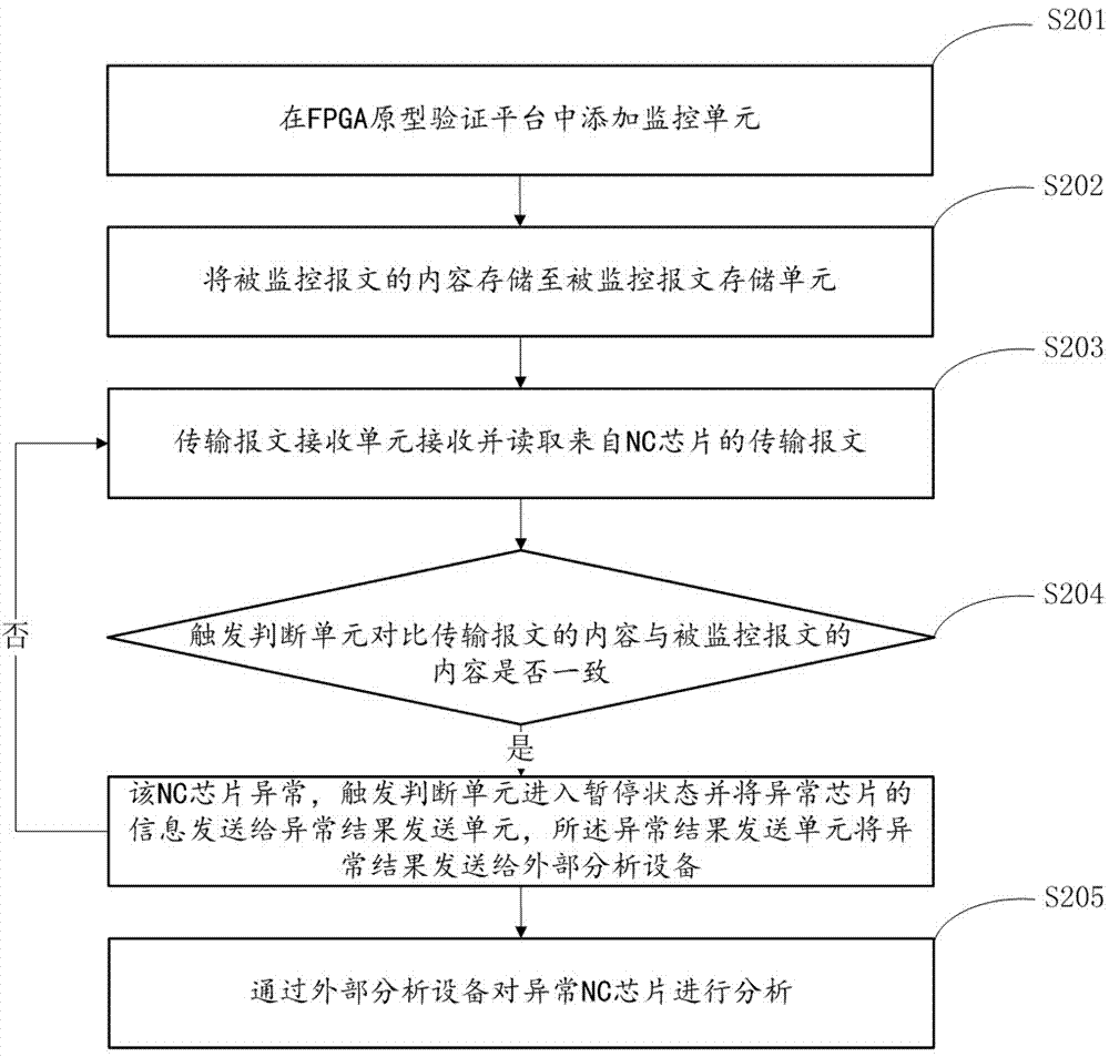
[0036] Please refer to figure 2 , A method to improve the efficiency of FPGA prototype verification, including the following steps:

[0037] Step 201: Add a monitoring unit to the FPGA prototype verification platform. The monitoring unit includes: a monitored message storage unit, a transmission message receiving unit, a trigger judgment unit, and an abnormal result sending unit;

[0038] Step 202: Store the content of the monitored message in the monitored message storage unit;

[0039] Step 203: The transmission message receiving unit receives and reads the transmission message from the NC chip;

[0040] Step 204: The trigger judgment unit compares whether the content of the transmitted message is consistent with the content of the monitored message. If they are consistent, the NC chip is abnormal, the trigger judgment unit enters the pause state, and the information of the abnormal chip is sent to the abnormal result sending unit , The abnormal result sending unit sends the abnor...


PUM


Abstract

The invention relates to the technical field of chip prototype verification and especially relates to a device and method for increasing FPGA prototype verification efficiency. The invention discloses a device for increasing the FPGA prototype verification efficiency. The device comprises a monitoring unit. The monitoring unit further comprises a monitored message storage unit, a transmission message receiving unit, a trigger judgment unit and an abnormal result sending unit, wherein the monitored message storage unit is used to store contents of a monitored message; the transmission message receiving unit is used to receive and read a transmission message from an NC chip; and the trigger judgment unit is used to judge whether contents of the transmission message are consistent with the contents of the monitored message. The invention also discloses a method for increasing the FPGA prototype verification efficiency. By the invention, a chip design department can analyze and position problems rapidly, and the verification efficiency of an FPGA prototype platform can be increased greatly.

Description

Technical field [0001] The invention relates to the technical field of chip prototype verification, in particular to a device and method for improving the efficiency of FPGA prototype verification. Background technique [0002] A lot of professional verification work is required from chip design to tapeout. Once the verification is incomplete, there may be problems in the chip that cannot be remedied after tapeout. In order to better verify the design of the chip, an FPGA prototype platform is usually built for verification, and the correctness of the function of the Node Controller (NC) chip in a real environment can be verified, which can make up for the inability of the soft simulation to be fully and quickly verified. Defects. Validate the system design, on the one hand, verify the availability and feasibility of multi-channel computers, verify the high-speed interface hardware PCB design and debugging, and verify the effectiveness of the mechanical structure and heat dissip...

Claims


Application Information

Patent Timeline
Patent Type & Authority Applications(China)
IPC IPC(8): G06F17/50
CPCG06F30/34
Inventor 王棚辉乔英良
Owner INSPUR SUZHOU INTELLIGENT TECH CO LTD
Why Eureka
Try Eureka