Iron palm degreasing device for brake pad manufacturing
A technology of brake pads and iron palms, which is applied in the field of iron palm oil removal devices for brake pad manufacturing, and can solve the problems of wear and tear of iron palms.
- Summary
- Abstract
- Description
- Claims
- Application Information
AI Technical Summary
Problems solved by technology
Method used
Image
Examples
Embodiment 1
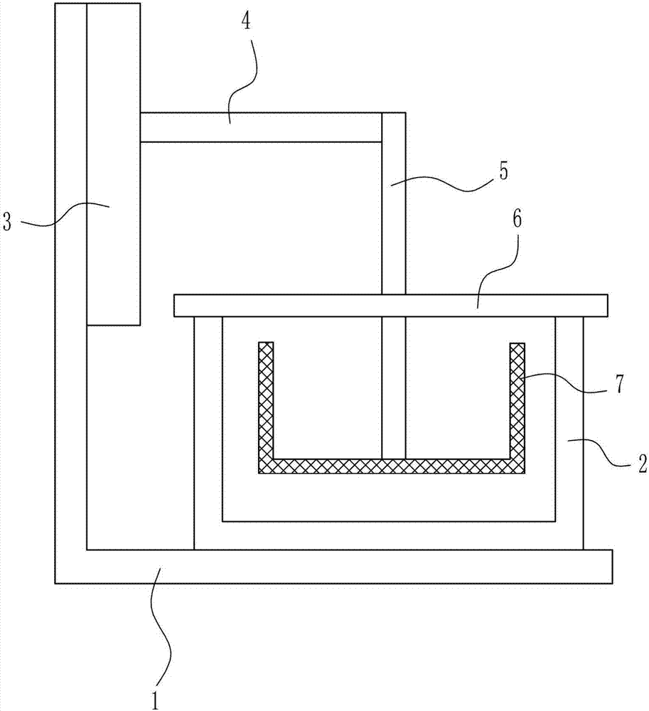
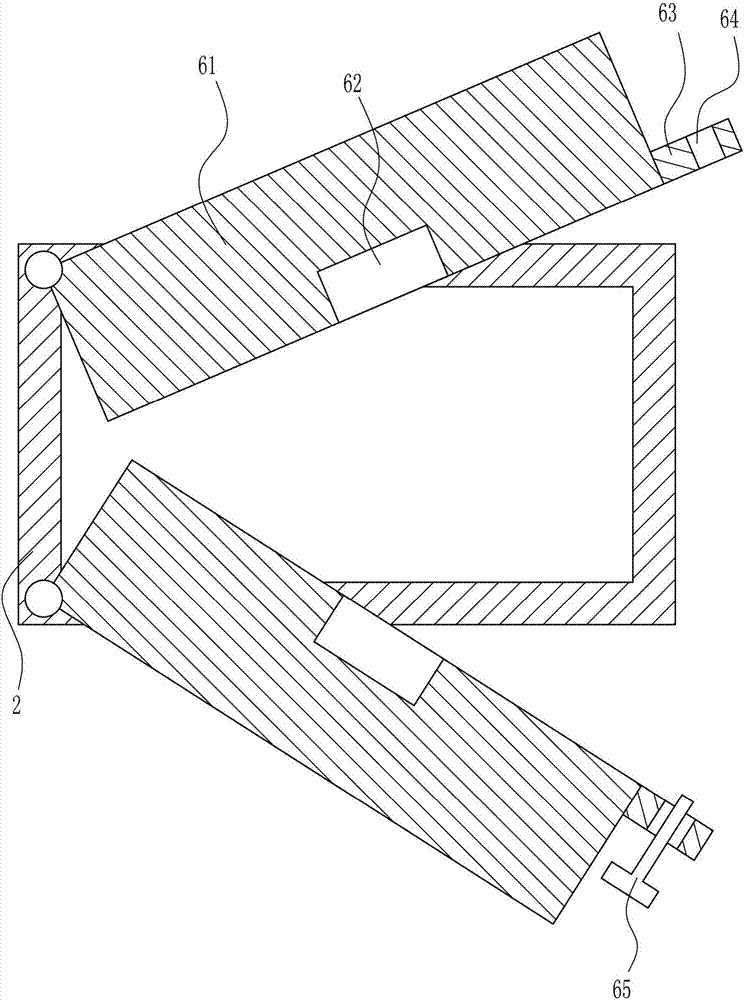
[0040] An iron palm degreasing device for brake pad manufacturing, such as Figure 1-7 As shown, it includes a frame 1, an oil removal tank 2, a lifting mechanism 3, a connecting rod 4, a lifting rod 5, a switch mechanism 6 and a first cylindrical filter frame 7, and the right side of the bottom of the frame 1 is connected with an oil removal tank 2 , the upper left wall of the frame 1 is connected with a lifting mechanism 3, the upper right side of the lifting mechanism 3 is connected with a connecting rod 4, the right end of the connecting rod 4 is connected with a lifting rod 5, and the bottom end of the lifting rod 5 is connected with a first cylindrical The filter screen frame 7, the first cylindrical filter screen frame 7 is located in the oil removal tank 2, and the top of the oil removal tank 2 is connected with a switch mechanism 6.
Embodiment 2
[0042] An iron palm degreasing device for brake pad manufacturing, such as Figure 1-7 As shown, it includes a frame 1, an oil removal tank 2, a lifting mechanism 3, a connecting rod 4, a lifting rod 5, a switch mechanism 6 and a first cylindrical filter frame 7, and the right side of the bottom of the frame 1 is connected with an oil removal tank 2 , the upper left wall of the frame 1 is connected with a lifting mechanism 3, the upper right side of the lifting mechanism 3 is connected with a connecting rod 4, the right end of the connecting rod 4 is connected with a lifting rod 5, and the bottom end of the lifting rod 5 is connected with a first cylindrical The filter screen frame 7, the first cylindrical filter screen frame 7 is located in the oil removal tank 2, and the top of the oil removal tank 2 is connected with a switch mechanism 6.
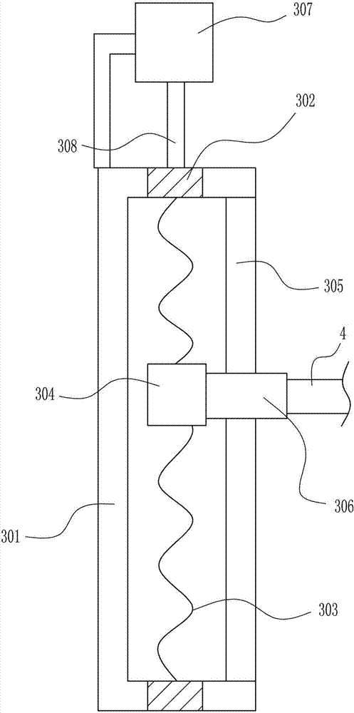
[0043] Lifting mechanism 3 comprises installation frame 301, first bearing block 302, screw mandrel 303, nut 304, first slide rail 305,...
Embodiment 3
[0045] An iron palm degreasing device for brake pad manufacturing, such as Figure 1-7 As shown, it includes a frame 1, an oil removal tank 2, a lifting mechanism 3, a connecting rod 4, a lifting rod 5, a switch mechanism 6 and a first cylindrical filter frame 7, and the right side of the bottom of the frame 1 is connected with an oil removal tank 2 , the upper left wall of the frame 1 is connected with a lifting mechanism 3, the upper right side of the lifting mechanism 3 is connected with a connecting rod 4, the right end of the connecting rod 4 is connected with a lifting rod 5, and the bottom end of the lifting rod 5 is connected with a first cylindrical The filter screen frame 7, the first cylindrical filter screen frame 7 is located in the oil removal tank 2, and the top of the oil removal tank 2 is connected with a switch mechanism 6.
[0046] Lifting mechanism 3 comprises installation frame 301, first bearing block 302, screw mandrel 303, nut 304, first slide rail 305,...
PUM
 Abstract
Description
Claims
Application Information
 - R&D
- Intellectual Property
- Life Sciences
- Materials
- Tech Scout
- Unparalleled Data Quality
- Higher Quality Content
- 60% Fewer Hallucinations
Browse by: Latest US Patents, China's latest patents, Technical Efficacy Thesaurus, Application Domain, Technology Topic, Popular Technical Reports.
© 2025 PatSnap. All rights reserved.Legal|Privacy policy|Modern Slavery Act Transparency Statement|Sitemap|About US| Contact US: help@patsnap.com


