
Steel rail damping fastener used for depot line of metro depot

A technology for damping fasteners and rails, which is applied in the directions of rails, fixed rails, roads, etc., can solve the problems of increasing the amount of rail buffer sinking, environmental vibration pollution, etc., and meets the limit of installation conditions and the height of fasteners. , The effect of ensuring driving safety and high-level vibration isolation performance

Active Publication Date: 2017-07-07
BEIJING INVESTMENT & TECH BEIJING CO LTD
View PDF7 Cites 7 Cited by
  • Summary
  • Abstract
  • Description
  • Claims
  • Application Information

AI Technical Summary

Problems solved by technology

[0007] The present invention solves the deficiencies of the prior art, and provides a rail damping fastener with reasonable structural design and novelty for the inner line of the subway depot, which can not only directly replace the existing common fasteners for the inner line of the subway depot, but also The cushioning sinking of the rail can be increased without increasing the lateral displacement of the rail head, which not only ensures the safety of driving, but also has a high vibration isolation capability, which can effectively solve the problem caused by the operation of the train in the development of the superstructure property. Environmental Vibration Pollution

Method used


Image

  • Steel rail damping fastener used for depot line of metro depot
  • Steel rail damping fastener used for depot line of metro depot
  • Steel rail damping fastener used for depot line of metro depot

Examples


Embodiment Construction

[0025] The present invention will be described in detail below in conjunction with the accompanying drawings and specific embodiments.

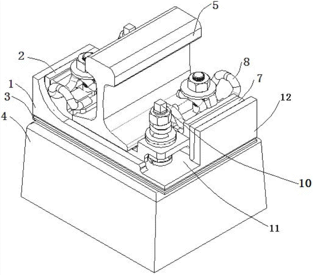
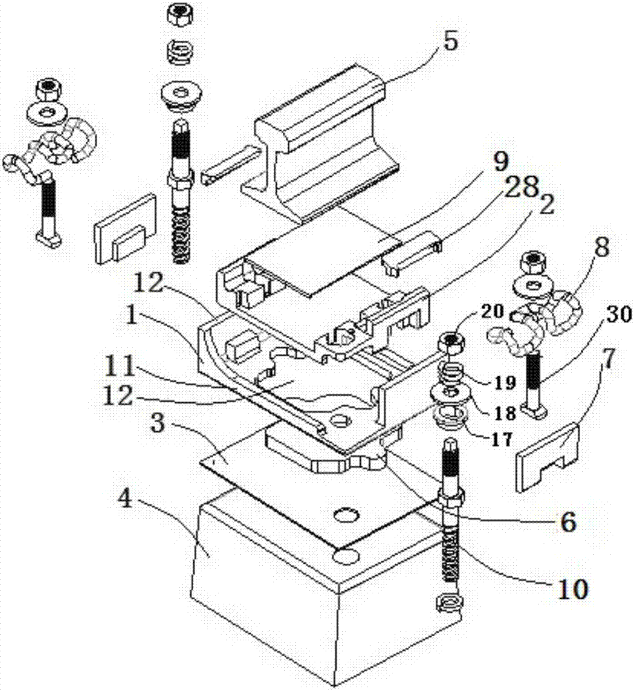
[0026] A rail vibration damping fastener used for the inner line of the subway depot, the structure is as follows figure 1 , figure 2 As shown, the rail damping fasteners include:

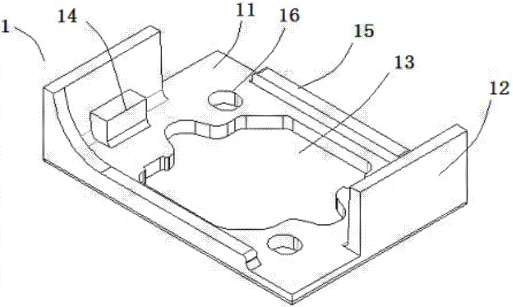
[0027] The base 1 is arranged on the sleeper 4. The base 1 has a base iron backing plate 11 and a shoulder 12 extending laterally from the base iron backing plate. The shoulder 12 is used to limit the lateral direction of the floating iron backing plate 2 Displacement, the base iron backing plate 11 is provided with a Chinese-shaped cavity 13; the under-board backing plate 3 is clamped between the base iron backing plate 11 and the sleeper 4; the base iron backing plate 11 and the under-board backing plate 3 pass through the double 10 nails on the head screw track are fastened on the sleeper 4;

[0028] The vibration isolation pad 6 is clamped between the iron...


PUM


Abstract

The invention discloses a steel rail damping fastener used for a depot line of a metro depot. The steel rail damping fastener comprises a base, a base plate under a plate, a vibration insulation cushion, a floating iron base plate and a lateral displacement constraint layer. The base is arranged on a rail bearing. The base plate under the plate is clamped between a base iron base plate and the rail bearing. The vibration insulation cushion is clamped between the base iron base plate and the base plate under the plate and arranged to be like a Chinese character 'zhong' and extends out of a cavity arranged to be like the Chinese character 'zhong'. The floating iron base plate is arranged on the base. The lateral displacement constraint layer is clamped between the side wall of the floating iron base plate and a blocking shoulder. The floating iron base plate is floated by the vibration insulation cushion and the lateral displacement constraint layer, namely the floating iron base plate does not make contact with the base iron base plate. The steel rail damping fastener can constrain transverse movement and vertical movement of a steel rail, namely the vibration insulation cushion constrains the vertical buffering capacity of the steel rail, and the lateral displacement constraint layer limits transverse movement of a railhead. The mutual influence of the two constraints is low, and the rigidity values, in the two directions, of the fastener can be independently designed according to actual requirements, so that the good vibration insulation is achieved under the condition that traveling safety is guaranteed.

Description

technical field [0001] The invention belongs to the technical field of vibration-damping fasteners for urban rail transit, and relates to rail vibration-damping fasteners, in particular to a rail vibration-damping fastener used for inner lines of subway depots. Background technique [0002] When developing the superstructure property of the subway depot that has been put into normal operation, the vibration of the superstructure will exceed the standard due to the operation of the subway. At this time, an effective control measure is to replace the ordinary fasteners in the depot with relatively strong fasteners. Vibration-absorbing fasteners with good vibration isolation capabilities. [0003] The trains running in the depot are not only at low speed, but also empty, so the inner line of the depot generally adopts smaller 50Kg / m steel rails, and does not make seamless treatment, and the fasteners and sleepers used are also light and compact, such as DJK5-1 Type fasteners o...

Claims


Application Information

Patent Timeline
IPC IPC(8): E01B9/62E01B9/68E01B19/00
CPCE01B9/62E01B9/688E01B19/00
Inventor 田振清郝伟亚高一轩王小兵蔡骋蔡灏肖中岭蔡锦辉毛刚吉沛杰
Owner BEIJING INVESTMENT & TECH BEIJING CO LTD
Learn More