conjoined structure building

A technology of conjoined structure and main structure, applied in the direction of buildings, building types, building components, etc., can solve the problems of insufficient utilization of truss materials and low stress level of truss webs

Active Publication Date: 2020-05-22
深圳华森建筑与工程设计顾问有限公司
View PDF5 Cites 0 Cited by
  • Summary
  • Abstract
  • Description
  • Claims
  • Application Information

AI Technical Summary

Problems solved by technology

[0004] The purpose of the present invention is to provide a conjoined structure building to solve the problems of insufficient utilization of truss materials and low stress level of truss web members in the prior art due to the direct rigid connection between the end of the truss and the main building

Method used


Image

  • conjoined structure building
  • conjoined structure building
  • conjoined structure building

Examples


Embodiment 1

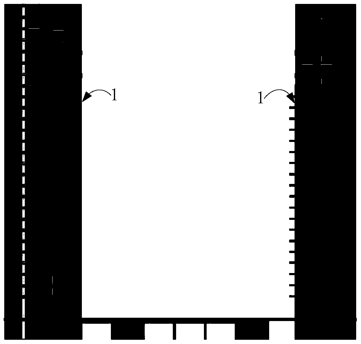
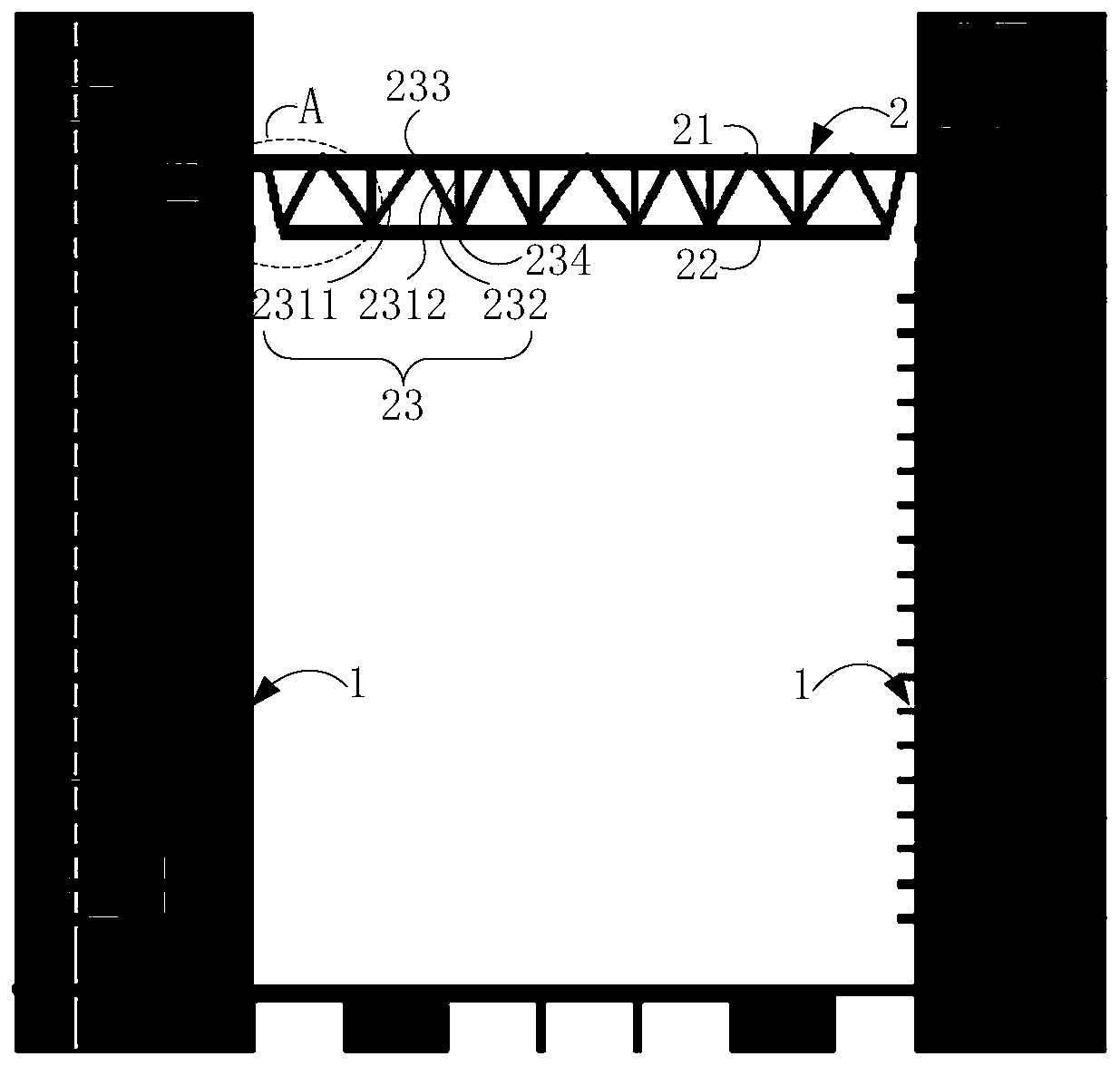
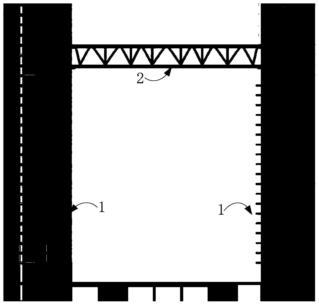
[0095] This embodiment provides a conjoined structure building, combining Figure 1 to Figure 10 As shown, the conjoined structure building includes two main structures 1 arranged at intervals, and a connecting body truss 2 fixed between the two main structures 1 . Such as figure 2 As shown, the connecting body truss 2 includes an upper chord 21 , a lower chord 22 , and a web 23 connected between the upper chord 21 and the lower chord 22 . combine Figure 1 to Figure 3 As shown, the conjoined structure building is obtained through the following construction methods:

[0096] Respectively construct the main structure 1 and the connecting body truss 2;

[0097] Hinge: connect the ends on both sides of the upper chord 21 of the connecting body truss 2 ( figure 2 middle, left and right ends) are respectively hinged with the parts to be connected on the main structure 1, and the ends on both sides of the lower chord 22 are disengaged from the parts to be connected on the main...

Embodiment 2

[0116] The difference between this embodiment and Embodiment 1 is that: Figure 11 , Figure 12 As shown, in order to strengthen the strength of the end of the upper chord 21 and the strength of the support part 24, in this embodiment, a horizontal reinforcement plate 241 is fixedly connected to the lower edge of the support part 24, and the horizontal reinforcement plate 241 is connected to the outermost two The vertical steel plates 212 jointly form the support portion 24 to increase the strength of the support portion 24 . In the subsequent construction steps, when the connecting body truss is bent and deformed, since the two vertical steel plates are connected by a horizontal reinforcement plate, the two vertical steel plates can be jointly stressed, preventing the deformation of the connecting body truss and only a single vertical steel plate In the case of more stress.

[0117] In order to further enhance the strength of the end of the upper chord 21, two transverse st...

Embodiment 3

[0119] This embodiment provides a conjoined structure building, combining Figure 13 to Figure 24 As shown, the conjoined structure building includes two main structures 1 arranged at intervals, and a connecting body truss 2 fixed between the two main structures 1 . Such as Figure 14 As shown, the connecting body truss 2 includes an upper chord 21 , a lower chord 22 , and a web 23 connected between the upper chord 21 and the lower chord 22 . The conjoined structure building is obtained through the following construction methods:

[0120] Respectively construct the main structure 1 and the connecting body truss 2;

[0121] Articulation: as Figure 14 As shown, the ends on both sides of the upper chord 21 (ie Figure 14 middle, left and right ends) are respectively hinged with the parts to be connected on the main structure 1, and the ends on both sides of the lower chord 22 are disengaged from the parts to be connected on the main structure 1 respectively;

[0122] Constr...


PUM


Abstract

The invention relates to the technical field of building structure engineering, in particular to a connected structure building. The connected structure building comprises at least two main structures arranged in a spaced mode, and a connection body truss fixedly connected between the main structures, wherein the connection body truss comprises an upper chord member, a lower chord member and a web member connected between the upper chord member and the lower chord member. The connected structure building is obtained according to the following construction method. The method comprises the steps that end parts on the two sides of the upper chord member are hinged to to-be-connected portions on the main structures correspondingly; the end portions of the two sides of the lower chord member are disengaged from the to-be-connected portions on the main structures correspondingly; standing is conducted, the connection body truss is bent and deformed under the action of gravity loads, and the end portions of the two sides of the upper chord member rotate; and the end portions, finishing rotation, of the two sides of the upper chord member are rigidly connected with the to-be-connected portions on the main structures, and the end portions of the two sides of the lower chord member are rigidly connected with the to-be-connected portions on the main structures correspondingly. The connected structure building has the excellent anti-seismic property and can sufficiently use truss materials.

Description

technical field [0001] The invention relates to the technical field of building structure engineering, in particular to connected structure buildings. Background technique [0002] In a conjoined structure building, the truss used to connect the main buildings on both sides usually adopts a steel truss structure. In order to effectively resist the earthquake action and enhance the seismic performance of the conjoined structure building, the rigid connection form is directly adopted between the ends of the upper and lower chords of the steel truss and the main building. [0003] When the span height of the truss is relatively large, the end nodes of the truss must not only bear the vertical action from the gravity load, but also bear the horizontal action caused by factors such as earthquake and wind loads, resulting in complex stress conditions and high stress levels. The size of the truss end nodes needs to be greatly increased, and the amount of steel used should be signi...

Claims


Application Information

Patent Timeline
Patent Type & Authority Patents(China)
IPC IPC(8): E04H1/00E04B1/38E04B1/24E04B1/98E04H9/02
CPCE04B1/24E04B1/38E04H1/00E04H9/024
Inventor 曹伟良李安张良平张民锐
Owner 深圳华森建筑与工程设计顾问有限公司
Why Eureka
Try Eureka