
A straight-plate built-in cryopump structure with three-stage adsorption structure

A technology of adsorption structure and adsorption plate, which is applied in the direction of pumps, liquid displacement machines, machines/engines, etc., can solve the problems that the pumping speed of the cryopump cannot meet the requirements, the long-term operation of the cryopump is unfavorable, and the heat load increases, etc. The effect of shortening, convenient matching, and reducing heat load

Active Publication Date: 2019-01-08
SOUTHWESTERN INST OF PHYSICS +1
View PDF9 Cites 0 Cited by
  • Summary
  • Abstract
  • Description
  • Claims
  • Application Information

AI Technical Summary

Problems solved by technology

[0004] At present, the non-standard cryopumps of large-scale devices usually adopt the herringbone radiation shielding structure. The herringbone radiation shielding structure can effectively block the heat radiation from the external environment to the cold plate, but for the limited vacuum chamber and vacuum of the neutral beam injector The requirements for pumping speed, the analysis method and the Monte Carlo method calculation results show that no matter how large the area of ​​the condensation adsorption plate is when the herringbone shielding structure is used, the actual pumping speed of the cryopump cannot meet the requirements; when the louver structure is used as the shielding structure, the conductance increases , although the actual pumping speed is close to the requirement, the heat load directly transmitted from the outside to the condensation adsorption plate also increases significantly, which is not conducive to the long-term operation of the cryopump

Method used


Image

  • A straight-plate built-in cryopump structure with three-stage adsorption structure
  • A straight-plate built-in cryopump structure with three-stage adsorption structure
  • A straight-plate built-in cryopump structure with three-stage adsorption structure

Examples


Embodiment Construction

[0035] The technical solutions of the present invention will be further described in detail below in conjunction with the accompanying drawings and embodiments.

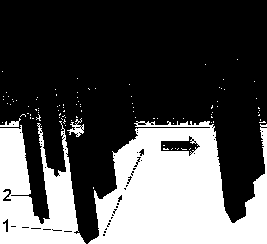
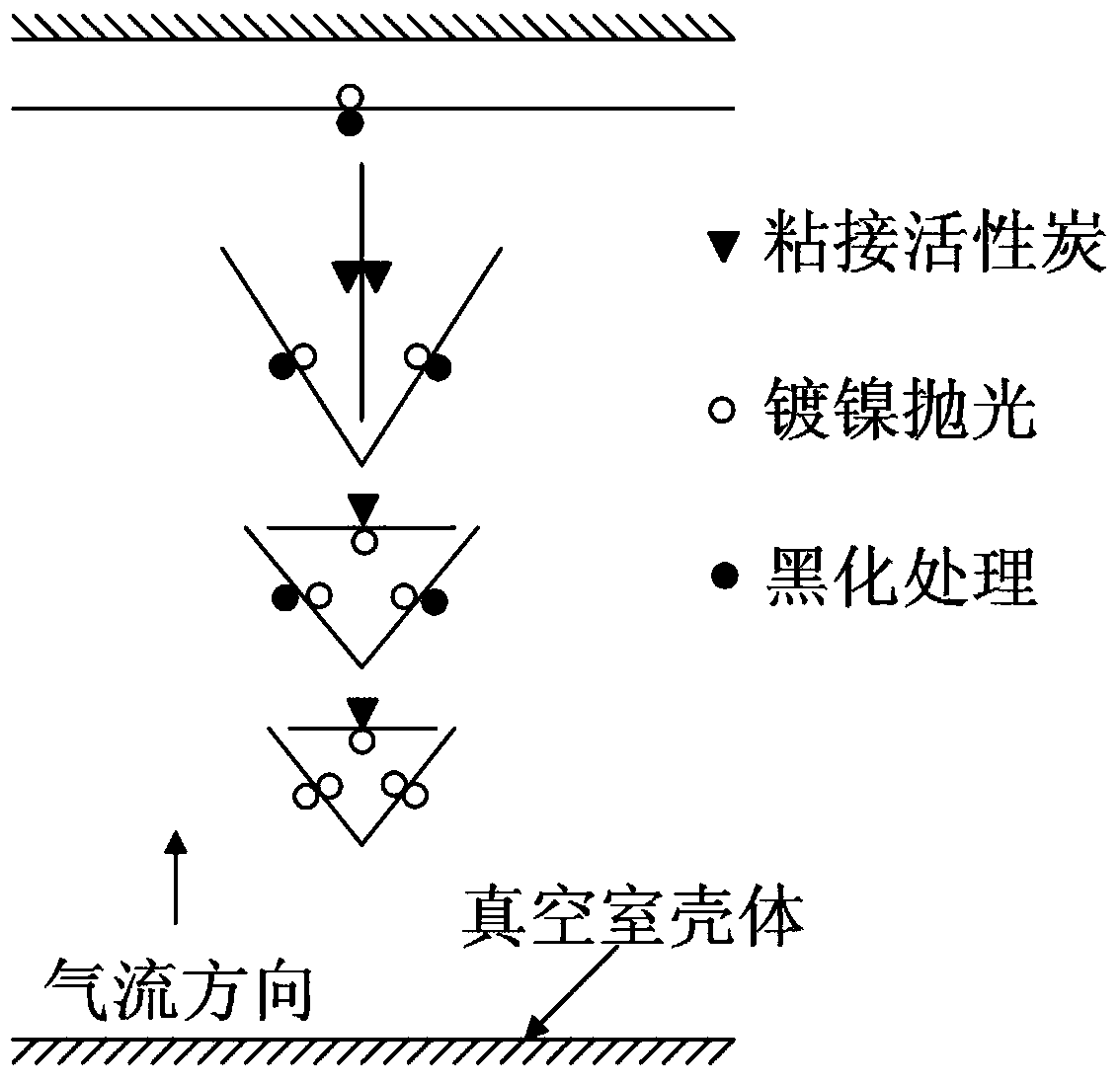
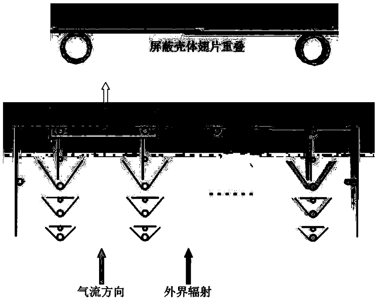
[0036] The present invention is a straight-plate built-in cryopump structure with a three-stage adsorption structure, which is applied to the vacuum differential system of the neutral beam injector in the controlled nuclear fusion experiment. The design idea of ​​the present invention is a combination of herringbone and louver radiation shielding structures Advantages and disadvantages, considering the limited space in the vacuum chamber of the neutral beam injector, a straight-type three-stage adsorption built-in cryopump was developed. Its core is a three-stage adsorption structure, including three V-shaped radiation shielding plates and three condensation adsorption plates. . Specifically include the following aspects:

[0037] (1) The adsorption structure is composed of a radiation shielding plate and a condensa...


PUM


Abstract

The invention provides a straight plate type built-in low-temperature pump structure with three levels of suction structures. The straight plate type built-in low-temperature pump structure with the three levels of suction structures is designed through reasonable arrangement for the conditions that the requirement for the suction speed is high and the space of a vacuum chamber is limited. The contradiction between heat load and gas flow conductance is effectively solved, the high suction speed is achieved in the limited space, and the operation cost is controlled. The three levels of suction structures comprise three levels of radiation shield plates and three levels of condensation suction plates. The multiple suction units are vertically assembled, independent from one another and form a suction array which is surrounded by a radiation shield shell at the liquid nitrogen temperature. Gas flow conductance is greatly improved through the gap between every two adjacent suction units. Compared with an inverted-Y-shaped structure, gas flow conduction is improved by 30-40%, the requirement for the suction speed in the limited space is met, different surface treatment technologies are adopted on the surfaces at different positions, heat radiation on the condensation suction plates is reduced, and the whole liquid nitrogen consumption is reduced.

Description

technical field [0001] The invention belongs to the technical field of vacuum obtaining equipment, and in particular relates to a large straight-plate built-in cryogenic pump with a three-stage adsorption structure. Background technique [0002] Neutral beam injection heating is an effective auxiliary heating chamber method in controlled nuclear fusion experiments. The gas is ionized in the discharge chamber to form plasma, which is then extracted by the extraction-acceleration system. When it passes through the neutralizer, it collides with the background gas and ionizes. , to perform neutral conversion, and the neutralized high-energy neutral particles are injected into the plasma center of the tokamak through the drift pipe to play a heating role. Pulse gas supply is required in the ion source discharge chamber and neutralizer, while the transmission path of high-energy neutral particles requires a high-vacuum environment. The entire beamline forms a vacuum differential s...

Claims


Application Information

Patent Timeline
Patent Type & Authority Patents(China)
IPC IPC(8): F04B37/08
CPCF04B37/08
Inventor 杨宪福刘伟成曹建勇
Owner SOUTHWESTERN INST OF PHYSICS
Learn More