Manual pressure-maintaining and skipping floating reversing valve for tractor

A tractor and reversing valve technology, applied in the field of hydraulic reversing valve, can solve the problems of troublesome maintenance, complex structure, large product volume, etc., and achieve the effects of reducing static settlement, reducing processing difficulty and improving processing accuracy

Active Publication Date: 2017-07-07
江苏力源液压机械有限公司
View PDF10 Cites 10 Cited by
  • Summary
  • Abstract
  • Description
  • Claims
  • Application Information

AI Technical Summary

Problems solved by technology

Now that the horsepower of agricultural tractors is getting bigger and bigger, the agricultural machinery that needs to be lifted is getting heavier and heavier, and users have higher and higher requirements for the internal leakage of the reversing valve, while the ordinary reversing valve is through the gap between the valve body and the valve core. Therefore, the traditional reversing valve can no longer meet the needs of users; although the internal leakage of the hydraulic valve can be reduced by adding a hydraulic lock, the current agricultural machinery is becoming more and more complicated, and many agricultural machinery All tractors require the tractor to have a floating function of the oil cylinder, because ordinary hydraulic locks are opened by pressure, so the system is in a state of pressure relief when the floating position is in place, and ordinary hydraulic locks cannot be used. They cannot have both, which has plagued various manufacturers for a long time; Although the independent distributor used in the existing tractor can solve the problem, the product has a large volume and complex structure, the failure rate has always been high, and the connection is complicated, and the internal space of the tractor is very small. Once a problem occurs, it is very troublesome to repair

Method used


Image

  • Manual pressure-maintaining and skipping floating reversing valve for tractor
  • Manual pressure-maintaining and skipping floating reversing valve for tractor
  • Manual pressure-maintaining and skipping floating reversing valve for tractor

Examples


Embodiment Construction

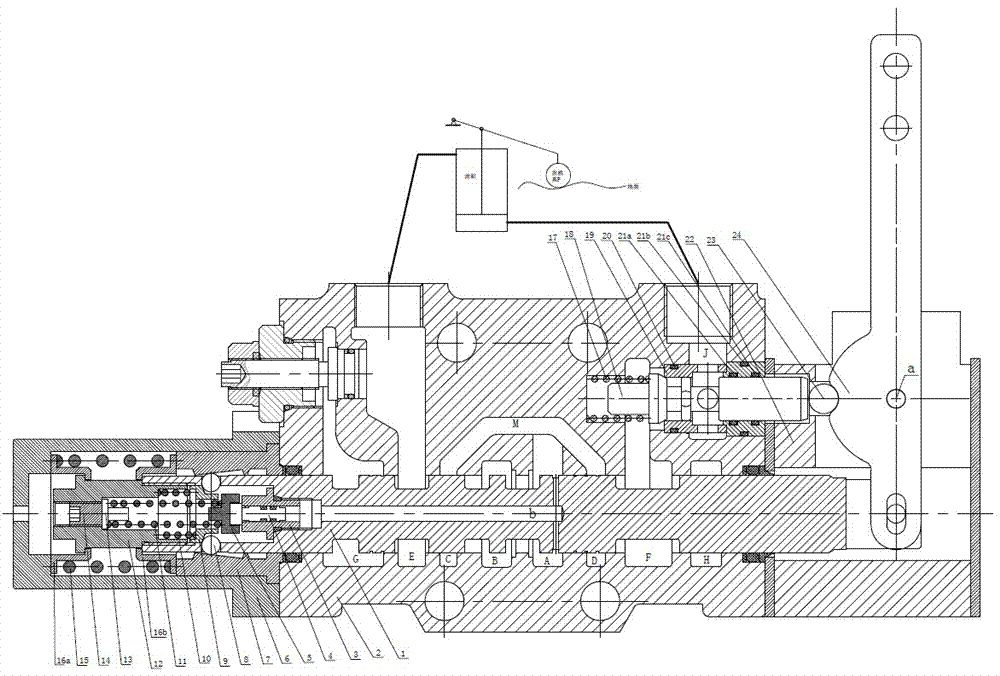
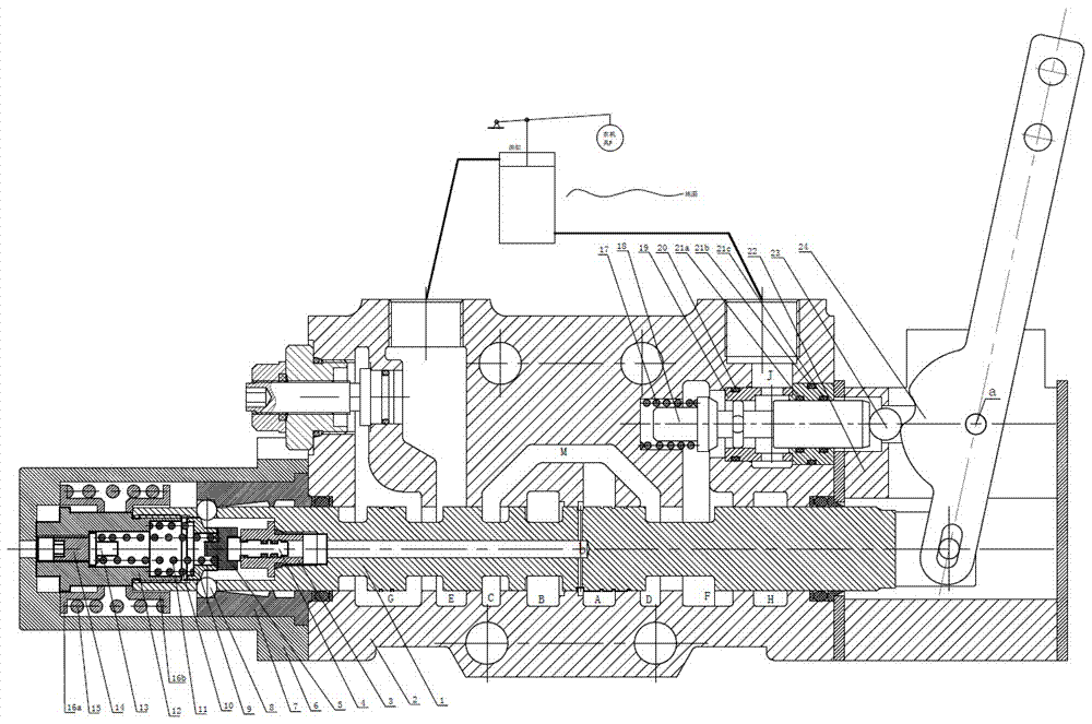
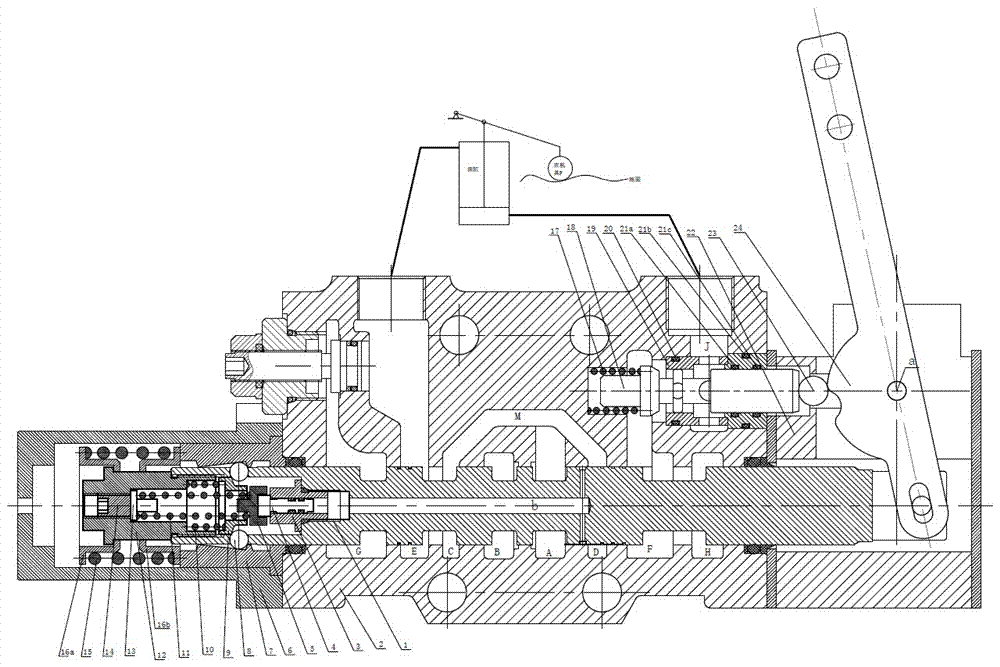
[0026] The technical solutions of the present invention will be further described below in conjunction with the accompanying drawings.

[0027] Such as Figure 1-5 As shown, the tractor manual pressure-holding jump floating reversing valve includes a valve core 1, a valve body 2, a front end cover 6 and a rear end cover 22. The valve core 1 is assembled in the valve body 2, and the front and rear ends of the valve body 2 are respectively Assemble the front end cover 6 and the rear end cover 22; it is characterized in that it also includes an oil passage conversion lock arranged in the valve body, a cam handle mechanism arranged in the rear end cover, a jump mechanism arranged in the valve core and a The positioning mechanism in the cover; the oil passage conversion lock includes a lock core 18 and a lock body 19, and the lock body 19 is assembled in the valve body 2 and is guaranteed by No. 1 to No. 4 sealing rings 20, 21a, 21b, and 21c. The cavity is in a sealed state, and t...


PUM


Abstract

The invention discloses a manual pressure-maintaining and skipping floating reversing valve for a tractor. The manual pressure-maintaining and skipping floating reversing valve for the tractor comprises a valve element (1), a valve body (2), a front end cover (6) and a rear end cover (22), wherein the valve element (1) is assembled in the valve body (2), and the front end cover (6) and the rear end cover (22) are assembled at the front end and the rear end of the valve body (2) correspondingly. The manual pressure-maintaining and skipping floating reversing valve for the tractor is characterized in that the reversing valve further comprises an oil duct switching lock arranged in the valve body, a cam handle mechanism arranged in the rear end cover, a skipping mechanism arranged in the valve element and a positioning mechanism arranged in the front end cover. The manual pressure-maintaining and skipping floating reversing valve for the tractor is compact in structure and flexible in reversing and has reliable functions, and the problem of settling, caused by internal leakage of an existing sliding reversing valve, of large agricultural implements on the rear portion of the tractor in the farming process is solved.

Description

technical field [0001] The invention relates to a hydraulic reversing valve, in particular to a tractor manual pressure-holding, jumping and floating reversing valve, which is integrated into a multi-way valve connection and is mainly used in high-horsepower tractors. Background technique [0002] The hydraulic reversing valve refers to the free switching of the oil circuit through the reversing of the valve core in the valve body through the corresponding groove between the valve body and the valve core, changing the direction of the oil circuit, and realizing the work of the actuator such as the oil cylinder. Now that the horsepower of agricultural tractors is getting bigger and bigger, the agricultural machinery that needs to be lifted is getting heavier and heavier, and users have higher and higher requirements for the internal leakage of the reversing valve, while the ordinary reversing valve is through the gap between the valve body and the valve core. Therefore, the t...

Claims


Application Information

Patent Timeline
Patent Type & Authority Applications(China)
IPC IPC(8): F15B13/02
CPCF15B13/024
Inventor 石妙鑫
Owner 江苏力源液压机械有限公司
Why Eureka
Try Eureka