Zero leakage external firing heat engine

A zero-leakage, heat-engine technology, applied in hot-gas variable capacity engine devices, mechanical equipment, engine components, etc., can solve the problems of small Stirling engine power/weight ratio, low thermal conversion efficiency of internal combustion engines, and inability to achieve zero leakage. , to achieve the effect of high conversion rate, simple structure and low noise

Inactive Publication Date: 2010-12-15
雷涛
View PDF4 Cites 7 Cited by
  • Summary
  • Abstract
  • Description
  • Claims
  • Application Information

AI Technical Summary

Problems solved by technology

[0005] The purpose of the present invention is to provide a zero-leakage type external combustion heat engine. The present invention is to overcome the low heat conversion efficiency (between 20% and 40%) of existing internal combustion engines, and discharge a large amount of polluting gases into the air due to incomplete combustion. problems, and the existing Stirling engine still has problems such as low power / weight ratio, and difficult sealing to achieve zero leakage, etc.

Method used


Image

  • Zero leakage external firing heat engine
  • Zero leakage external firing heat engine

Examples


specific Embodiment approach 1

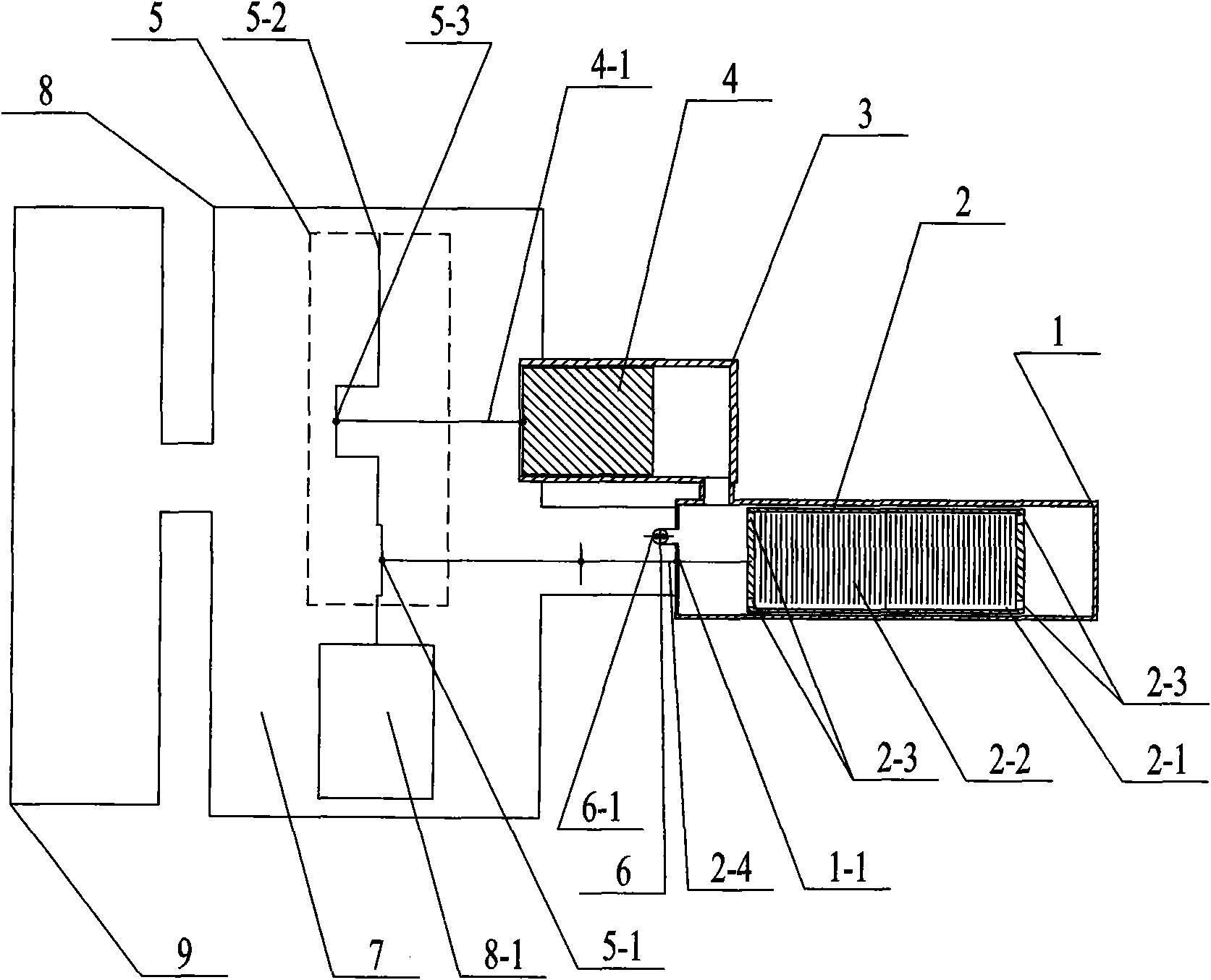
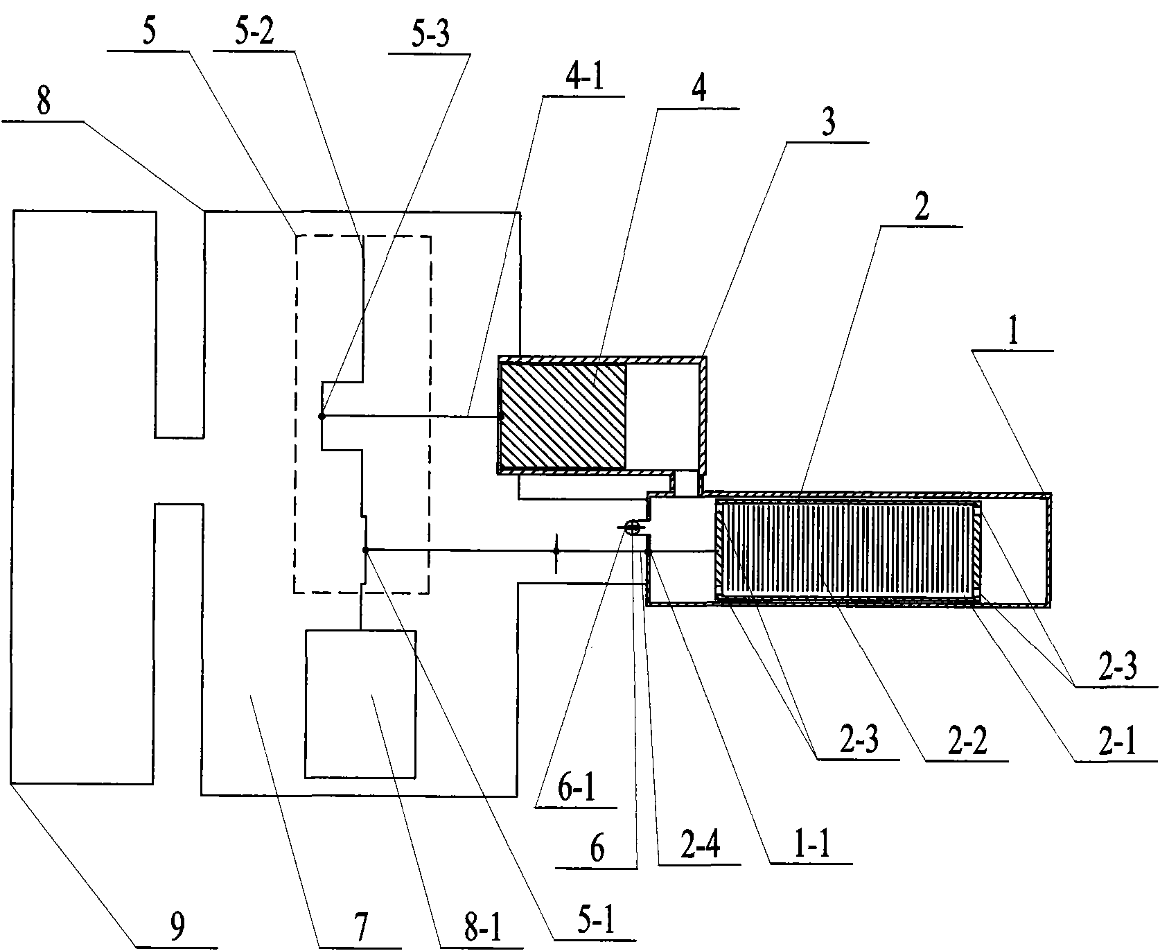
[0016] Specific implementation mode one: combine figure 1 Describe this embodiment, this embodiment is made up of air-guiding cylinder chamber 1, air-guiding piston 2, working cylinder chamber 3, working piston 4, flywheel crankshaft assembly 5, ventilation valve 6, gas working medium 7, and airtight housing 8;

[0017] The inner cavity 2-1 of the gas guide piston 2 is provided with a multi-layer heat storage and gas conduction metal mesh 2-2, and each of the two ends of the gas guide piston 2 has a through hole 2-3 connected with the inner cavity 2-1. , the air guide piston 2 is arranged in the air guide cylinder chamber 1, and the connecting rod 2-4 of the air guide piston 2 passes through the sliding seal sleeve 1-1 at one end of the air guide cylinder chamber 1 and connects with the first part of the flywheel crankshaft assembly 5 The crank rod 5-1 is connected in rotation, and when the crankshaft 5-2 of the flywheel crankshaft assembly 5 rotates, it drives the air guide p...

specific Embodiment approach 2

[0024] Specific implementation mode two: combination figure 1 Describe this embodiment, the difference between this embodiment and specific embodiment 1 is that the conduction starting point of the ventilation valve 6 is when the crankshaft 5-2 in the flywheel crankshaft assembly 5 rotates and the air guide piston 2 moves to the air guide cylinder cavity 10 degrees before the top of the hot end. Other components and connections are the same as in the first embodiment.

specific Embodiment approach 3

[0025] Specific implementation mode three: combination figure 1 Describe this embodiment, the difference between this embodiment and specific embodiment 1 is that the conduction starting point of the ventilation valve 6 is when the crankshaft 5-2 in the flywheel crankshaft assembly 5 rotates and the air guide piston 2 moves to the air guide cylinder cavity 1 5 degrees before the top of the hot end. Other components and connections are the same as in the first embodiment.


PUM


Abstract

The invention discloses a zero leakage external firing heat engine, which relates to the technical field of heat energy conversion. The zero leakage external firing heat engine aims to solve the problem of the low heat conversion efficiency and insufficient combustion of the conventional internal combustion engine, the problem that the conventional Stirling engine has a low power-to-weight ratio and zero leakage cannot be realized due to difficulties in sealing, and the like. An outward ventilation valve is connected with a closed chamber formed by communicating an air guiding cylinder chamber with the upper part of a dowork cylinder chamber; a conduction start point of the ventilation valve is that an air guiding piston moves between positions which are 20 degrees in front of and behind the top of the high temperature end of the air guiding cylinder chamber; the conduction angle of the ventilation valve 6 is between 5 and 30 degrees; and all movable sealing positions and the outward ventilation port of the ventilation valve are sealed in a closed shell. The zero leakage external firing heat engine can directly and efficiently convert combustion heat energy of fuels into mechanical energy and realize zero leakage; the internal movable sealing part technology of the engine can meet working requirements by adopting the prior art; the power-to-weight ratio is extremely high; and the convention efficiency is 20 percent to 80 percent.

Description

technical field [0001] The invention relates to the technical field of converting thermal energy into mechanical energy. Background technique [0002] Existing internal combustion engines are widely used in various fields, among which the number of automotive applications is the largest, which brings a lot of convenience to human life, but its heat / engine conversion efficiency is generally between 20% and 40%, and the remaining 60% ~80% of the heat energy cannot be used and needs to be discharged outside. At the same time, because the fuel cannot be completely burned, the exhaust gas will emit a large amount of polluting gas into the air, which will seriously pollute the air. According to statistics, these are the main causes of global warming. one of the reasons. It has brought irreparable loss and damage to the future living environment of human beings. [0003] The Stirling engine was invented by Stirling in 1816. Stirling engines are unique heat engines in that their ...

Claims


Application Information

Patent Timeline
Patent Type & Authority Applications(China)
IPC IPC(8): F02G1/043F02G1/053
CPCF02G2253/03F02G2253/00F02G2253/04F02G1/043F02G2253/02F02G2243/30
Inventor 雷涛
Owner 雷涛
Why Eureka
Try Eureka