Magnetic fluid sealing structure for reciprocating motion

A magnetic fluid sealing and reciprocating motion technology, which is applied to the sealing of the engine, engine components, mechanical equipment, etc., can solve the problems of poor pressure resistance, achieve strong pressure resistance, reduce pollution, and improve purity

Inactive Publication Date: 2018-04-10
GUANGXI UNIVERSITY OF TECHNOLOGY
View PDF10 Cites 6 Cited by
  • Summary
  • Abstract
  • Description
  • Claims
  • Application Information

AI Technical Summary

Problems solved by technology

[0005] Regardless of whether single-stage sealing or multi-stage sealing is used, the main effect is the sealing performance, which has little effect on the pressure resistance performance, and the pressure resistance performance of the entire sealing structure is poor.

Method used


Image

  • Magnetic fluid sealing structure for reciprocating motion

Examples


Embodiment Construction

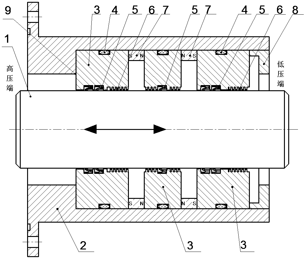
[0027] Such as figure 1 As shown, a magnetic fluid sealing structure for reciprocating motion, including a hollow housing 2, a reciprocating shaft 1 arranged in the inner cavity of the housing 2, in the radial direction between the outer surface of the reciprocating shaft 1 and the inner wall of the housing 2 At least one permanent magnet 7 is provided, and pole shoes 3 are respectively provided on both sides of each permanent magnet 7 . The inner surface of the pole shoe 3 is provided with pole teeth 6, and there is a gap between the pole teeth 6 and the outer surface of the reciprocating shaft 1, and the gap is filled with magnetic fluid.

[0028] One end of the inner cavity of the housing 2 is provided with a step 9, the pole shoe 3 closest to the high-voltage end abuts against the step 9, and the pole shoe 3 closest to the low-pressure end is tightly sealed in the housing 2 through the end cover 8 cavity.

[0029] There is at least one groove around the inner surface of ...


PUM


Abstract

The invention discloses a magnetic fluid sealing structure for the reciprocating motion. The magnetic fluid sealing structure comprises a hollow shell, a reciprocating shaft arranged in an inner cavity of the shell and at least one permanent magnet. Pole shoes are arranged on the two sides of each permanent magnet. At least one groove is formed around the inner circle face of each pole shoe, and aY-shaped sealing ring is arranged in each groove. Pole teeth are arranged on the inner circle faces of the pole shoes, gaps exist between the pole teeth and the outer surface of the reciprocating shaft, and magnetic fluid is injected into the gap positions. Through combined usage of the magnetic fluid and the Y-shaped sealing rings, a sealing structure excellent in pressure resisting performanceand sealing performance is formed. Accordingly, due to the fact that the magnetic fluid seal has a dustproof function, pollution to the Y-shaped sealing rings from outside impurities is reduced, purity of sealed media is improved, the service life of the sealing ring is prolonged to the maximum degree, and the requirements for zero leakage and long service life are met.

Description

technical field [0001] The invention relates to a magnetic fluid sealing structure for reciprocating motion. Background technique [0002] The existing magnetic fluid sealing structure for the reciprocating movement of the shaft generally includes a housing with a hollow cavity, a shaft, a permanent magnet and a pole shoe are arranged between the shaft and the housing for magnetic fluid sealing, and the inner ring of the pole shoe is provided with pole teeth. [0003] One of the methods to improve the pressure resistance performance of the magnetic fluid seal is to increase the number of magnetic sources in the magnetic circuit of the magnetic fluid seal and improve the shape of the pole piece, such as the sealing device described in the patents with publication numbers CN105003654A and CN206617583U. Although the sealing performance of the two sealing devices described in the above documents has been greatly improved compared with ordinary magnetic fluid, the prior art still...

Claims


Application Information

Patent Timeline
Patent Type & Authority Applications(China)
IPC IPC(8): F16J15/43
Inventor 杨小龙陈帆孙彭郝付祥何美丽
Owner GUANGXI UNIVERSITY OF TECHNOLOGY
Why Eureka
Try Eureka