
Intelligent iron tower safety detector

A technology for safety detection and iron towers, which is applied in the direction of measuring devices, instruments, closed-circuit television systems, etc., can solve the problems of inability to communicate with iron towers for real-time monitoring and high monitoring costs, and achieve the effect of high degree of automation and high reliability

Pending Publication Date: 2017-07-07
武汉市中电慧通科技有限公司
View PDF10 Cites 2 Cited by
  • Summary
  • Abstract
  • Description
  • Claims
  • Application Information

AI Technical Summary

Problems solved by technology

[0003] The purpose of the present invention is to provide an intelligent iron tower safety detection device to solve the problems that the existing communication tower monitoring technology cannot monitor the communication tower in real time, the monitoring cost is high and manual inspection is required

Method used


Image

  • Intelligent iron tower safety detector
  • Intelligent iron tower safety detector

Examples


Embodiment 1

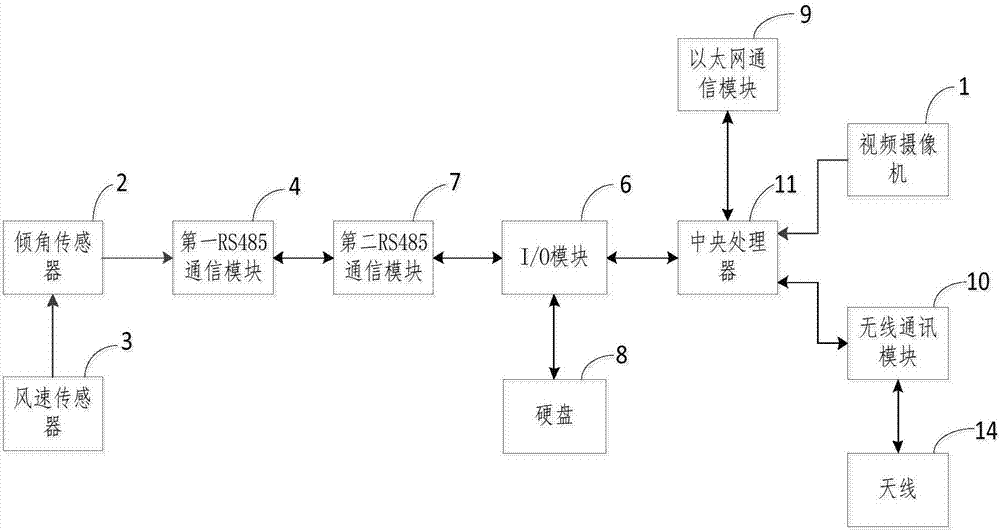
[0014] Such as figure 1 As shown, the smart tower safety detection device includes a video camera 1, an inclination sensor 2, a wind speed sensor 3, a first RS485 communication module 4, an I / O module 6, a second RS485 communication module 7, a hard disk 8, an antenna 14, an Ethernet A communication module 9 , a wireless communication module 10 and a central processing unit 11 . The first RS485 communication module 4 is connected with the processing module of the inclination sensor 2, the wind speed sensor 3 is connected with the processing module of the inclination sensor 2, and the central processing unit 11 is respectively connected with the video camera 1, the wireless communication module 10, and the I / O module 6. Both the RS485 communication module 7 and the hard disk 8 are connected to the I / O module 6 , and the antenna 14 is connected to the wireless communication module 10 . The inclination sensor 2 is fixedly installed on the communication tower, and the inclination...

Embodiment 2

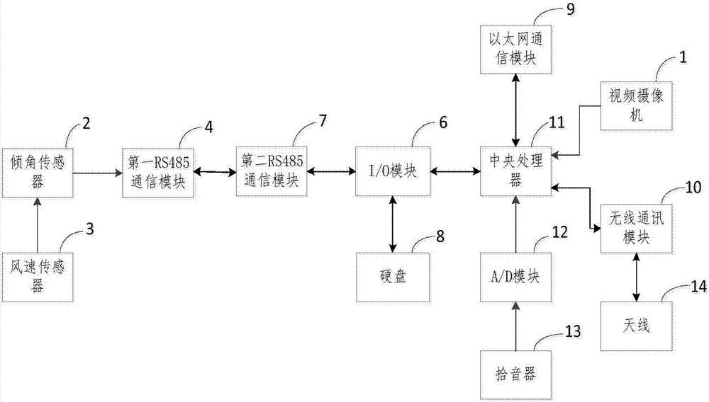
[0017] Such as figure 2As shown, this embodiment is based on Embodiment 1. The difference from Embodiment 1 is that the smart tower safety detection device in this embodiment includes a video camera 1, an inclination sensor 2, a wind speed sensor 3, and a first RS485 In addition to communication module 4, I / O module 6, second RS485 communication module 7, hard disk 8, antenna 14, Ethernet communication module 9, wireless communication module 10 and central processing unit 11, also includes lightning protection module (not shown) , pickup 13 and A / D module 12, pickup 13 is connected with central processing unit 11 by A / D module 12, the power supply input end of lightning protection module is connected with the power supply of intelligent iron tower safety detection device, video camera, inclination sensor, wind speed sensor , the power output terminal of the lightning protection module is connected to the ground. When any one of the power supply, frequency camera, inclination ...


PUM


Abstract

The invention relates to an intelligent iron tower safety detector. The detector comprises a video camera, an inclination angle sensor, a wind speed sensor, first and second RS485 communication modules, an I / O module, an antenna, a wireless communication module and a central processor; the first RS485 communication module and the wind speed sensor are connected with a processing module of the inclination angle sensor, the central processor is connected with the video camera, the wireless communication module and the I / O module, and the second RS485 communication module is connected with the I / O module; the antenna is connected with the wireless communication module; the inclination angle sensor senses changes of an inclination angle of an iron tower, converts change of the inclination angle to an electric inclination-angle signal, and sends the electric inclination-angle signal to the first RS485 communication module; and the central processor encodes received video, wind-speed 485 and inclination angle 485 signals, superposes the coded signals with time information, and sends the superposed signals to a cloud server via a wireless communication module. The detector is high in automatic degree and reliability, low in utilization cost and can avoid overturning accidents of the communication iron tower effectively.

Description

technical field [0001] The invention relates to the technical field of iron tower monitoring devices, in particular to an intelligent iron tower safety detection device. Background technique [0002] At present, there are more than 4 million iron towers in stock in the country. Taking communication iron towers as an example, some communication iron towers have been used for more than 10 years and the number of platforms is constantly increasing due to network needs. The design and use of communication iron towers requires up to 50 years. Metal corrosion, metal The impact of fatigue, even with a dangerous probability of one in 10,000 per year, will cause huge losses. The communication tower design standard refers to meteorological and geological records that occur once in 50 years. At present, various meteorological and address disasters that occur once in 100 years include blizzards, typhoons, floods, earthquakes, subsidence, mudslides, landslides and other natural disasters...

Claims


Application Information

Patent Timeline
Patent Type & Authority Applications(China)
IPC IPC(8): G01D21/02H04N7/18
CPCH04N7/18G01D21/02
Inventor 刘轶晧胡文斌丁滨
Owner 武汉市中电慧通科技有限公司
Learn More