

High frequency injection-based oxygen sensor internal resistor detection circuit
A technology of oxygen sensor and high-frequency injection, which is applied in the direction of measuring electrical variables, measuring resistance/reactance/impedance, instruments, etc., can solve problems such as inability to measure in real time, and achieve real-time detection and optimize the effect of output voltage
- Summary
- Abstract
- Description
- Claims
- Application Information
AI Technical Summary
Problems solved by technology
Method used
Image

Examples
Embodiment
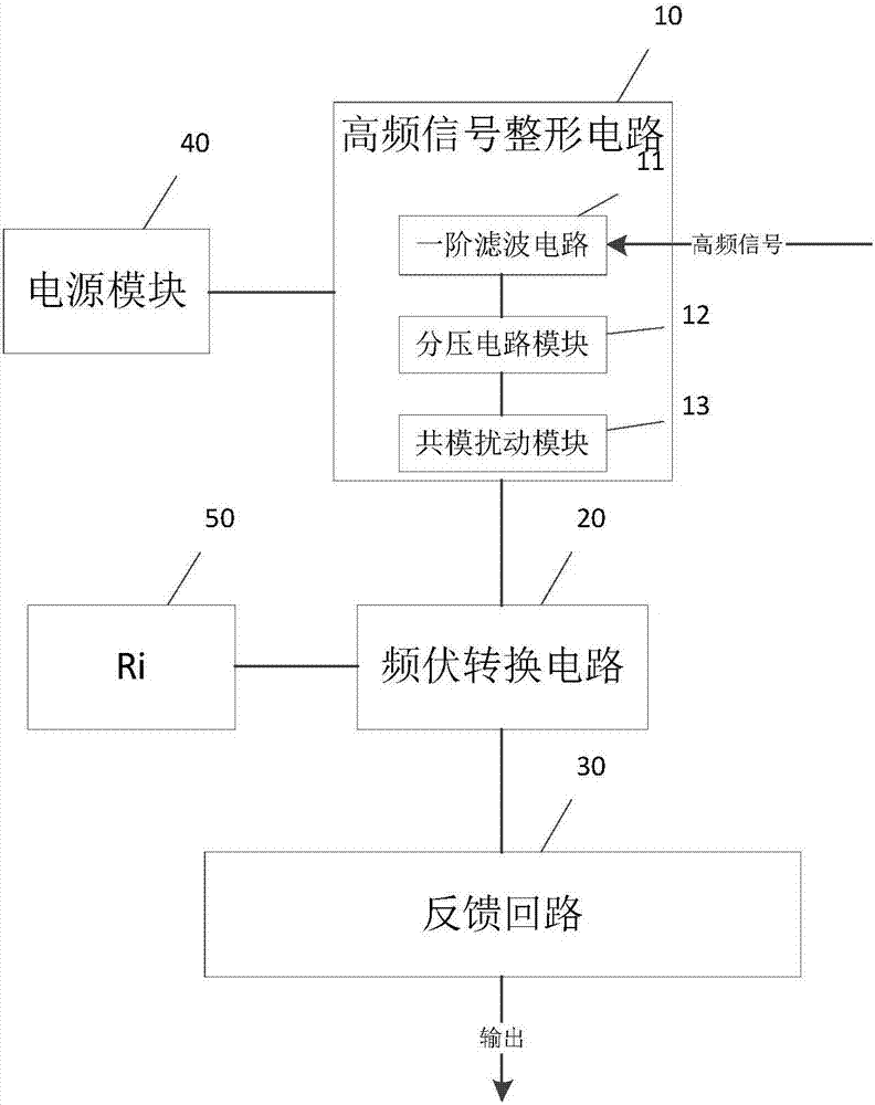
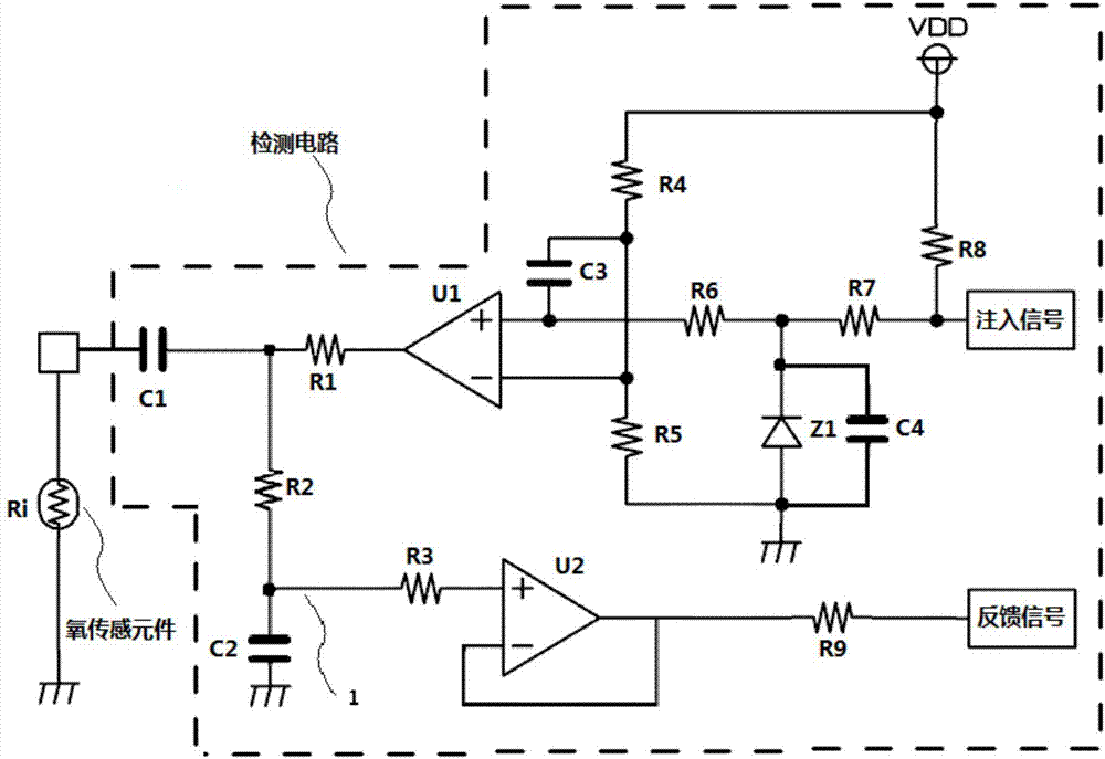
[0026] like Figure 1-2 As shown, a detection circuit for the internal resistance of an oxygen sensor based on high-frequency injection includes a high-frequency signal shaping circuit 10, a frequency-voltage conversion circuit 20, a feedback loop 30, an internal resistance Ri50 of the oxygen sensor, and a power supply for supplying power to the detection circuit Module VDD40, the high-frequency signal is input to the high-frequency signal shaping circuit 10, the output end of the high-frequency signal shaping circuit 10 is electrically connected to the input end of the frequency-voltage conversion circuit 20, and the frequency-voltage conversion circuit 20 is connected to the oxygen sensor The resistance Ri50 is electrically connected, and the output end of the frequency-to-voltage conversion circuit 20 is electrically connected to the input end of the feedback loop 30 .
[0027] In the above circuit:
[0028] High-frequency signal shaping circuit 10: used to receive high-fr...
PUM
 Abstract
Description
Claims
Application Information