Light guide plate, design method and dot distribution method thereof, and illumination device

A technology of light guide plate network point and design method, which is applied in the light guide, light guide, optics and other directions of the lighting system, can solve the problems of low practicability, high complexity, long cycle period of dynamic molecular method, etc., and achieve the effect of strong practicability

Active Publication Date: 2017-07-07
SHANGHAI SANSI ELECTRONICS ENG +2
View PDF7 Cites 9 Cited by
  • Summary
  • Abstract
  • Description
  • Claims
  • Application Information

AI Technical Summary

Problems solved by technology

However, the dynamic molecular method has a long cycle and takes a lot of time, and some people have also done experiments on the dots of equal radius, using the dynamic molecular method to do countless cycles. The final result is that all the molecules (dots) have reached an equilibrium state, resulting in A uniform dot distribution that backfires
Due to the high complexity of these tasks, the practicability is low, and most of them are still at the theoretical level.

Method used


Image

  • Light guide plate, design method and dot distribution method thereof, and illumination device
  • Light guide plate, design method and dot distribution method thereof, and illumination device
  • Light guide plate, design method and dot distribution method thereof, and illumination device

Examples


Embodiment 1

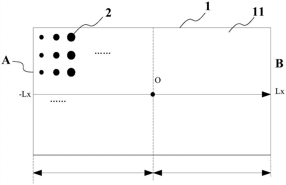
[0046] In this embodiment, the derivation and description are made for the case of a rectangular light guide plate, circular dots, the same dot spacing, and one-sided light entering with varying dot sizes:

[0047] First, step 1 is performed: obtaining the relational formula between the variable parameter of the screen size and the position of the screen. For circular dots, the size variable parameter is the radius (of course, it can also be represented by diameter). In other shapes of dot design, we only need to express the relationship between the dot size variable and the dot area in the design, for example, in square In the dot, it can be characterized by the side length. It should be noted that the size variable of the dot is preferred to only set one size variable. The next parameter is used as a variable, which can greatly reduce the amount of calculation. For the case of unilateral light input in this embodiment, we directly deduce the relationship between the dot rad...

Embodiment 2

[0082] The difference between this embodiment and Embodiment 1 lies in that the dot size of the light guide plate remains unchanged and the dot pitch changes. It is used to teach those skilled in the art to understand how the method of the present application can be deformed in the case of different variable types of the light guide plate.

[0083] Similarly, Step 1: obtain the relational formula between the variable parameter of the dot spacing and the position of the dot. Based on the same optical principle and basic formula, the equations (1)~(4) and (6) remain unchanged, and the filling rate formula (5) needs to be deformed due to the change of variables, and the interval between adjacent columns of dots changes. The interval variable is ΔL(x), the distance between each row is a constant b (if it is a square, it is also ΔL(x)), and the dots are circular, then the filling rate η(x) should be the area of ​​the circle divided by the area of ​​the rectangle :

[0084]

[...

Embodiment 3

[0091] The difference between embodiment 3 and embodiment 1 is that the light sources are arranged on both sides or the periphery of the light guide plate. It is used to teach those skilled in the art to understand deformation under the condition of multi-sided light entering.

[0092] Similarly, proceed to step 1: obtain the relational formula between the variable parameter of the dot size and the position of the dot. The method of deriving by the basic principle of optics is introduced in embodiment 1, which is also applicable. Based on the superposition principle of incoherent light, the luminous flux scattered by the dots can be divided into the sum of two parts. At this time, (1) and Equation (2) should be established for the two parts, so that two functions can be obtained. Mathematical calculation process is no longer repeated, those skilled in the art can carry out corresponding deformation according to the teaching of the method in embodiment 1 and embodiment 2, fina...


PUM


Abstract

The invention provides a light guide plate, a design method and dot distribution method thereof, and an illumination device. In the design method, a relation formula between a position of the light guide plate and dot parameters is obtained; any two positions of the light guide plate and corresponding dot parameter values are set, a constant whose physical meaning is not clear in the relation formula between the position of the light guide plate and the dot parameters is represented by a concrete physical quantity, and dot distribution of the light guide plate is obtained. Practical mathematical expressions of dot radius distribution under different conditions are obtained, and great convenience is provided for design of the light guide plate.

Description

technical field [0001] The invention relates to the technical field of lighting equipment, in particular to a design method of a light guide plate, a light guide plate, a network point distribution method and a lighting appliance. Background technique [0002] Compared with direct-type light guide plates, the biggest advantages of side-entry light guide plates are thinner thickness, lighter weight, and lower cost. At present, side-entry light guide plates are still the mainstream of light guide plate production, especially small and medium-sized light guide plates are almost all side-entry types. However, because the light enters the light guide plate from the edge of the side-entry light guide plate, it is easy to cause uneven brightness on the surface of the light guide plate. Therefore, the dot design becomes the key to the design of the side-entry light guide plate. [0003] There are many ways to design the dots of side-entry light guide plates, but in fact most manufac...

Claims


Application Information

Patent Timeline
Patent Type & Authority Applications(China)
IPC IPC(8): G02B6/00
CPCG02B6/004G02B6/005
Inventor 周士康陈春根杜金缪路平
Owner SHANGHAI SANSI ELECTRONICS ENG
Why Eureka
Try Eureka