

an indoor ventilation system
A technology for ventilation systems and air outlet pipes, applied in the field of ventilation systems, can solve the problems of single airflow level direction, poor comfort, high energy consumption, etc., and achieve the effects of stable airflow temperature, guaranteed energy consumption, and changeable wind direction
Active Publication Date: 2019-05-10
浙江立信建设集团有限公司
View PDF7 Cites 2 Cited by
- Summary
- Abstract
- Description
- Claims
- Application Information
AI Technical Summary
Problems solved by technology
[0004] Aiming at the problems of single air flow direction, poor comfort and high energy consumption in the indoor ventilation system in actual use, the purpose of the present invention is to propose an indoor ventilation system. The specific scheme is as follows:
Method used
View moreImage
Smart ImageViewing Examples

Examples
Embodiment 2
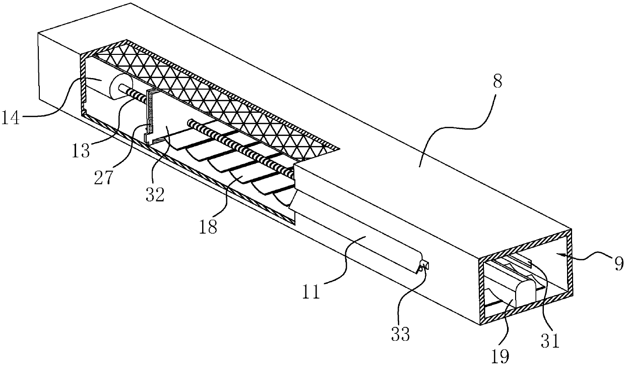
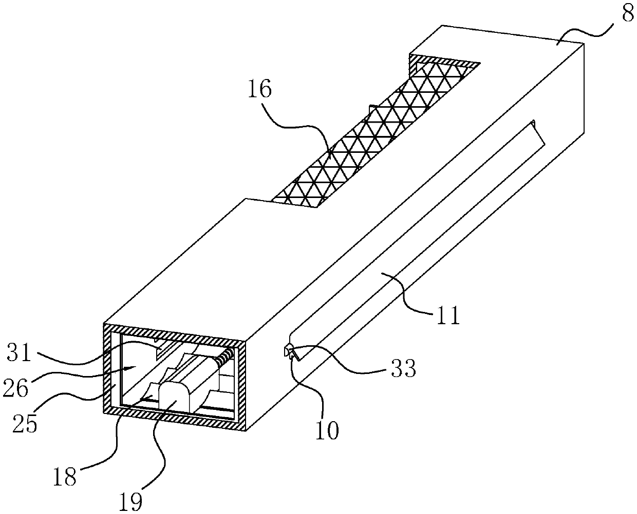
[0059] An indoor ventilation system, the difference from Embodiment 1 is that the first driving member includes an electromagnetic track arranged along the length direction of the air outlet pipe 8, and the wind shield 32 is provided with a magnetic block that matches the electromagnetic track and is electromagnetically controlled. The electromagnetic force on the track drives the movement. In the above technical solution, the position of the wind shield 32 can be precisely controlled by using the change of the current on the electromagnetic track, so that the air volume and air flow level of the entire indoor ventilation system can be precisely controlled.
Login to View More PUM
 Abstract
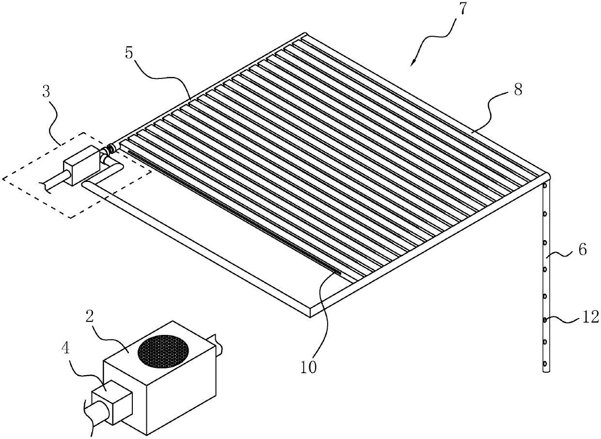
The invention discloses an indoor ventilation system which comprises a control component, a blower device, a pipeline component, a filtering component, an air intake pipe, an air returning pipe and an air flow control module, wherein the air flow control module is communicated with the air intake pipe and comprises a plurality of air outlet pipes, and the air outlet pipes are arranged on an indoor ceiling or wall in parallel; air outlet holes are formed in the side wall of each air outlet pipe along the length direction, and shutters used for regulating the air volume and the air direction of the air outlet pipe are arranged on each air outlet pipe; the air returning pipe is arranged on the indoor ceiling or wall, and air returning holes are formed in the air returning pipe; air draught is formed between the air outlet holes of the air outlet pipes and the air returning holes of the air returning pipe. The air outlet pipes are arranged in parallel, and air separating plates are arranged in the air outlet pipe in a sliding mode, so that the air discharge area of the air outlet holes of the air outlet pipes can be conveniently regulated and changed, and therefore the size of the indoor airflow is changed. The level change of the indoor airflow can be convenient to realize through the air outlet pipes arranged side by side.
Description
technical field [0001] The present invention relates to a ventilation system, more particularly, it relates to an indoor ventilation system. Background technique [0002] In terms of building structure, a ventilation system is usually provided to meet the living needs of the personnel in the inner room of the building. The existing indoor ventilation system is mainly composed of air intake equipment, filter equipment, air supply channels and exhaust equipment. Usually, in order to meet different usage requirements, some air purification equipment, heating and humidification equipment, etc. will be added to the above system. . [0003] For example, the Chinese patent whose patent announcement number is CN203687278U proposes a passive ventilation system for science and technology museum buildings, which mainly includes a building frame main body. Air supply channels are provided on both sides of the building frame main body, and a ventilation channel is provided at the bottom...
Claims
Login to View More Application Information
Patent Timeline
 Patent Type & AuthorityPatents(China)
IPC IPC(8): F24F7/08F24F13/30F24F11/64F24F11/77
CPCF24F7/08F24F11/30F24F11/58F24F11/62F24F11/79F24F13/30Y02B30/70
Inventor劳月清
Owner浙江立信建设集团有限公司