
Light field display device and method

A display device and display method technology, applied in optics, optical components, instruments, etc., can solve the problems of thick lenses, difficult high speed, high precision, low energy consumption, and small field of view, so as to achieve easy wearing and avoid human eyes Effects of fatigue and other physical discomfort

Active Publication Date: 2017-07-11
LIGHTIN INC
View PDF9 Cites 5 Cited by
  • Summary
  • Abstract
  • Description
  • Claims
  • Application Information

AI Technical Summary

Problems solved by technology

However, the structure of the device is complicated, and the stepping motor and the transmission mechanism are involved in the focusing, so it is difficult to achieve a balance in terms of high speed, high precision, and low energy consumption.
[0006] The U.S. patent with the publication number US201704574 discloses a compact head-mounted display system, which includes a waveguide lens and an imaging prism with a complex structure, but its field of view is small
The patent with the publication number WO2016081664A1 discloses a head-mounted display system with a large field of view, which includes an image source and a free-form surface mirror mask, but it is bulky; the Chinese patent with the publication number CN101359089 discloses a head-mounted display with a free-form surface prism System, including micro-display and free-form prism, but the lens of the device is thick and requires compensation mirror, which is not conducive to production and use

Method used


Image

  • Light field display device and method
  • Light field display device and method
  • Light field display device and method

Examples


Embodiment Construction

[0043] The present invention will be described in further detail below in conjunction with the accompanying drawings and embodiments.

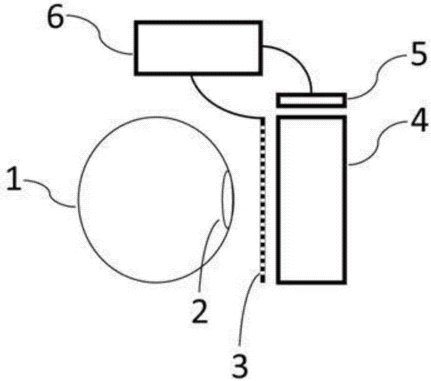
[0044] Such as figure 1 As shown, the light field display device of the present invention includes an image source 5 , a mixing module 4 , a transmissive spatial light modulator 3 and a control module 6 . The image source 5 is a 0.5-inch LCD, which can be selected from commercially available products; the hybrid module 4 is a thin transflective flat panel; the transmissive spatial light modulator 3 is a liquid crystal spatial light modulator and is equipped with a polarizer near the eyeball. A sheet with a thickness of 1mm, the same size as the hybrid module 4 used and placed close to the hybrid module 4, each independent unit of the transmissive spatial light modulator 3 is arranged in a two-dimensional array.

[0045] The optical path of the image light generated by the image source 5 used to represent the virtual information is adjusted by...


PUM


Abstract

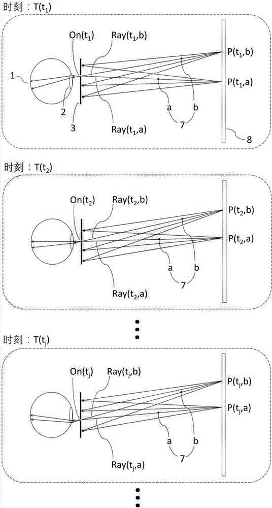
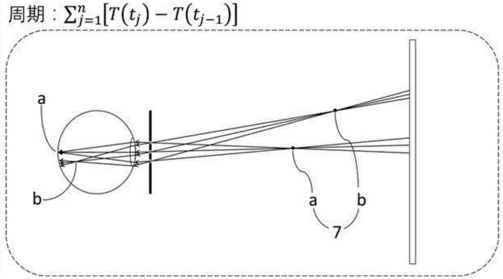
The invention discloses a light field display device and method, and the device comprises an image source which generates light representing virtual information; a mixing module which enables the light of the virtual information and external environment light to pass through the mixing module and a transmitting type spatial modulator to enter human eyes; the transmitting type spatial modulator which carries out the modulation of the light of the virtual information and external environment light according to a control signal of a control module; and the control module which synchronously controls the transmitting type spatial modulator and the image source, enables different independent units of the transmitting type spatial modulator to be opened or closed in an ordered manner, and enables the image source to display corresponding images in an ordered manner. The method comprises the step: quickly opening or closing different independent units in an ordered manner through the transmitting type spatial modulator, and building a simulation light field for to-be-represented virtual information. When a user see the to-be-represented virtual information through the simulation light field, there is no convergence adjustment conflicts, thereby avoiding the fatigue of human eyes and other physiological discomfort.

Description

technical field [0001] The invention relates to the technical field of virtual reality and augmented reality, in particular to a three-dimensional display device and a display method based on the light field principle. Background technique [0002] Virtual reality (Virtual Reality) technology is a display technology that presents virtual information in front of users more realistically and achieves the effect of "disgusting the real". It usually shields the external real environment and immerses users in the virtual world. Augmented Reality (Augmented Reality) technology is a display technology that superimposes virtual information on the real world, which enables users to observe the real environment outside at the same time. These technologies can be widely used in military, medical, education, manufacturing, entertainment and other fields. With the advancement of commercialization of related technologies, VR / AR devices are becoming more and more well-known to the public,...

Claims


Application Information

Patent Timeline
IPC IPC(8): G02B27/22
CPCG02B30/27
Inventor 张卓鹏魏一振
Owner LIGHTIN INC
Learn More