Method for mounting vehicle former face parts and vehicle

A front face and car technology, applied in the field of installing car front face parts, can solve problems such as relative position deviation

Active Publication Date: 2017-07-14
CHERY AUTOMOBILE CO LTD
View PDF4 Cites 7 Cited by
  • Summary
  • Abstract
  • Description
  • Claims
  • Application Information

AI Technical Summary

Problems solved by technology

In addition, when processing the mounting holes for mounting the front-end module assembly on the front end of the longitudinal beam, there is a large tolerance between the positions of the two mounting holes and the preset positions
[0006] In this way, due to the existence of the above-mentioned tolerances, there may be a large deviation in the relative positions of the various components of the front face of the car.

Method used


Image

  • Method for mounting vehicle former face parts and vehicle
  • Method for mounting vehicle former face parts and vehicle
  • Method for mounting vehicle former face parts and vehicle

Examples


Embodiment 1

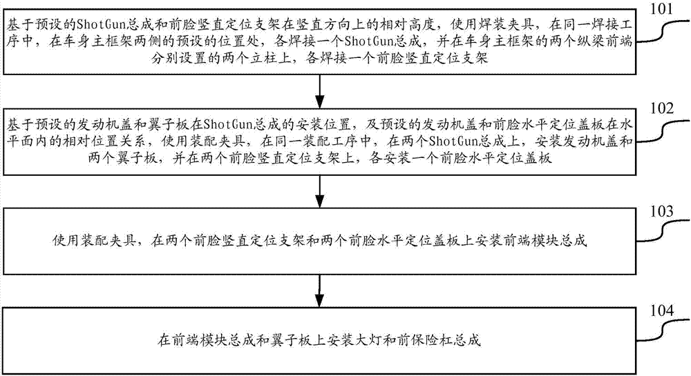
[0062] The invention provides a method for installing the front face parts of an automobile, the flow process of the method is as follows figure 1 As shown, the following steps may be included:

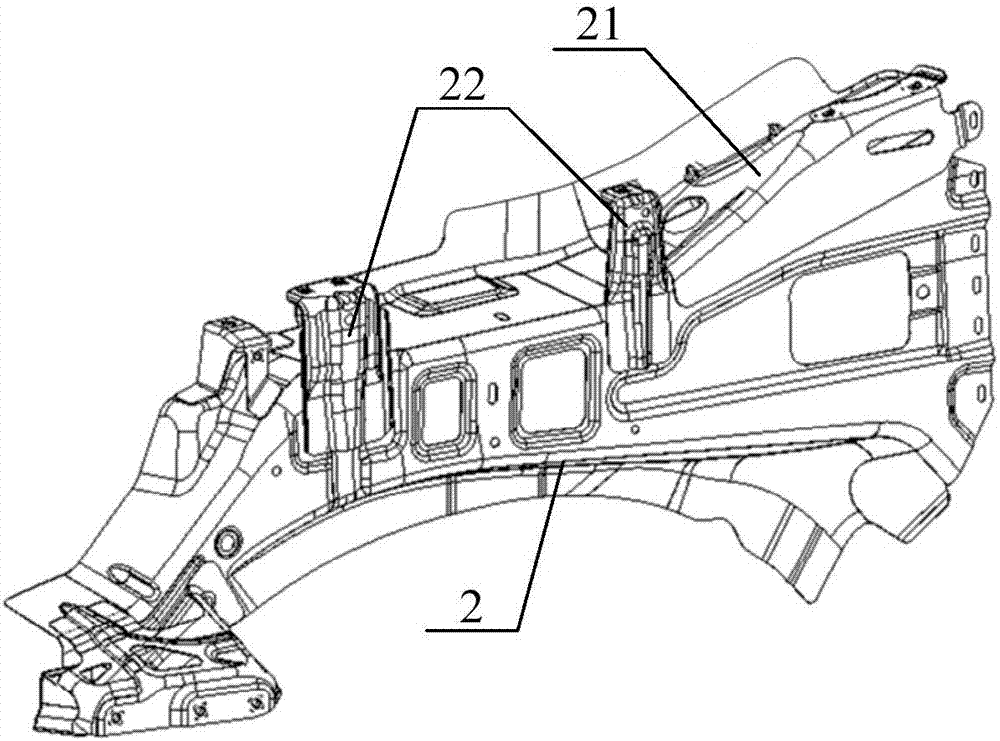
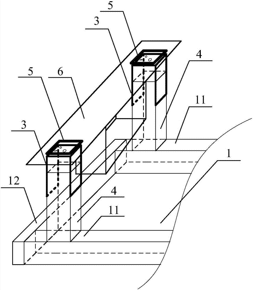
[0063] Step 101, based on the preset relative heights of the ShotGun assembly 2 and the vertical positioning bracket 3 of the front face in the vertical direction, using a welding jig, in the same welding process, the preset heights on both sides of the main frame 1 of the vehicle body position, each welding a ShotGun assembly 2, and on the two columns 4 respectively arranged at the front ends of the two longitudinal beams 11 of the vehicle body main frame 1, respectively welding a front face vertical positioning bracket 3.

[0064] Among them, the welding jig is an auxiliary welding tool, which is used to realize the relative positioning of two or more parts to be welded during the welding process. Specifically, during welding, use the synergy of positioning pins, clamping arms and ...

Embodiment 2

[0088] The present invention also provides an automobile, the front face part of the automobile can be installed using the method described in the first embodiment.

[0089] The car comprises a body main frame 1, an engine cover, a front-end module assembly 6, two ShotGun assemblies 2, two fenders, two front vertical positioning brackets 3, two front horizontal positioning covers 5 and Two headlights, and front bumper assembly, of which:

[0090] Two ShotGun assemblies 2 are installed at the preset positions of the body main frame 1; the front ends of the two longitudinal beams 11 of the body main frame 1 are respectively provided with a column 4, and each column 4 is respectively equipped with a front face vertical positioning bracket 3. Among them, the front face vertical positioning bracket 3 and the ShotGun assembly 2 meet the preset relative height in the vertical direction; the two fenders are respectively installed on the two ShotGun assemblies 2, and the engine cover i...


PUM


Abstract

The invention discloses a method for mounting vehicle former face parts and a vehicle, and belongs to the technical field of vehicles. The method comprises the steps that on the basis of the preset relative height of ShotGun assemblies and former face vertical positioning supports in the vertical direction, a welding clamp is used for welding one ShotGun assembly on each of the two sides of a vehicle body main framework, and one former face vertical positioning support is welded to each of two stand columns; on the basis of the preset relative position relation of an engine cover, fenders and former face horizontal positioning cover boards in the horizontal face, an assembly clamp is used for mounting the engine cover and the two fenders on the two ShotGun assemblies, and mounting one former face horizontal positioning cover board on each former face vertical positioning support; the assembly clamp is used for mounting a front-end module assembly on the two former face vertical positioning supports; and then other parts of a former face are mounted. By adoption of the method for mounting the vehicle former face parts and the vehicle, the technical problem that the tolerance generated during production and machining possibly causes large deviation of the relative positions of the vehicle former face parts can be solved.

Description

technical field [0001] The invention relates to the technical field of automobiles, in particular to a method for installing a front face part of an automobile and the automobile. Background technique [0002] Today, with the increasing development of science and technology and manufacturing, the competition in the automobile industry is becoming more and more fierce, and customers' requirements for appearance quality are also gradually improving. The matching size between the front face parts of the car is particularly important to the overall appearance of the car. The matching relationship between them not only affects the appearance of the car body, but also affects its performance. Front face parts mainly include engine cover and fenders, headlights, front bumper and front bumper outer covering parts. On the basis of ensuring the size of each part, these parts are ensured in the welding and installation process. The relative matching relationship of components on the b...

Claims


Application Information

Patent Timeline
Patent Type & Authority Applications(China)
IPC IPC(8): B62D65/02B62D65/04
CPCB62D65/02B62D65/026B62D65/04
Inventor 杨超徐晖王玉春郑莉芳杨杏花
Owner CHERY AUTOMOBILE CO LTD
Why Eureka
Try Eureka