

Method and device for controlling pitch of aircraft
An aircraft and mixed control technology, which is applied in the field of aircraft, can solve the problems that cannot be compensated, cannot control the pitch of the aircraft well, and cannot reduce the volume of the aircraft, so as to achieve the effect of improving stability
- Summary
- Abstract
- Description
- Claims
- Application Information
AI Technical Summary
Problems solved by technology
Method used
Image

Examples
no. 1 approach
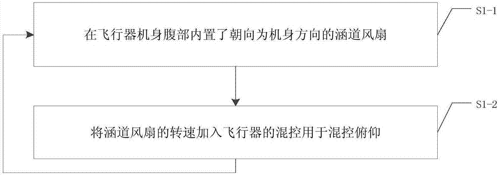
[0015] Such as image 3 Shown, method of the present invention comprises:
[0016] S1-1, a ducted fan 3 facing the direction of the fuselage is built in the belly of the aircraft fuselage.
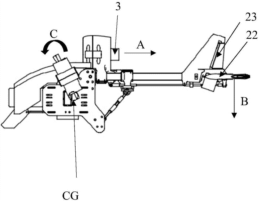
[0017] refer to Figure 1-2 , the ducted fan 3 blows the airflow to the rear of the fuselage, and the airflow direction is shown by arrow A. At the same time, the ducted fan 3 also makes up for the instability of the biaxial aircraft on the pitch (Pitch) axis.
[0018] If the position of the ducted fan 3 is far away from the center of gravity and the thrust is high, the fuselage will tend to roll forward, forming the torque M shown by the arc arrow C. How to use the existing flight control hybrid control empennage to dynamically offset this torque M is a difficult point.
[0019] Therefore, the position of the ducted fan 3 is as close as possible to the center of gravity of the aircraft. figure 1 The position marked by the middle dotted circle is the center of gravity CG of the aircra...
no. 2 approach
[0026] On the basis of the first embodiment, a second embodiment is proposed.
[0027] Such as Figure 4 Shown, method of the present invention comprises:
[0028] S2-1, a ducted fan 3 facing the direction of the fuselage is built in the belly of the aircraft fuselage.
[0029] S2-2, a horizontal stabilizer 22 is set at the tail of the aircraft, and the air flow blown backward by the ducted fan 3 is converted into a variable F.
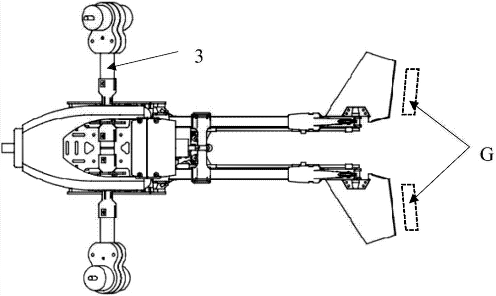
[0030] During the flight of the aircraft, under the control of the steering gear, the horizontal tail 22 can be figure 1 Rotate on the paper plane as shown, the airflow that duct fan 3 blows back ( figure 1 The direction shown by the middle arrow B) is transformed into a variable F, such as figure 1 . At the same time, if figure 2 As shown, the vicinity (shown by arrow G) behind the horizontal stabilizer 22 is a high-pressure zone.
[0031] S2-3, add the rotation speed of the ducted fan 3 and the angle of the horizontal stabilizer 22 to the mi...
no. 3 approach
[0042] Preferably, on the basis of the second embodiment, a vertical empennage 21 is arranged at the rear of the aircraft, and the vertical empennage 21 is located in front of the horizontal empennage 22, and the vertical empennage 21 can rectify the airflow in the front, so that the horizontal empennage 22 is better in the aerodynamic center generate torque.
[0043] Double vertical tail 21 is subject to flight control mixed control equally, double vertical tail 21 and double machine arm 3 (see figure 2 ) jointly control the yaw (Yaw) of the aircraft. When the aircraft enters the high-speed forward flight state (FFF), the yaw weight of the dual arms 3 becomes smaller, and the yaw weight of the double vertical tail fins 21 becomes larger. The above design allows the aircraft to achieve a tail flick similar to that of a car during high-speed flight. The throttle of the ducted fan is not controlled by the flight control and is completely manual, which can be understood as the ...
PUM
 Abstract
Description
Claims
Application Information