Wire arrangement restraint device for warp yarn arrangement

A restraining device and warp yarn technology, which is applied in warping machines, textiles, papermaking, manufacturing tools, etc., can solve problems such as the inability to maintain the yarn arrangement position well, achieve good results, reduce accidents and injuries, and operate in a safe space Effect

Active Publication Date: 2017-07-14
杭州凯秀纺织有限公司
View PDF6 Cites 0 Cited by
  • Summary
  • Abstract
  • Description
  • Claims
  • Application Information

AI Technical Summary

Problems solved by technology

[0004] The present invention aims at the disadvantage that the prior art cannot well maintain the stability of the yarn arrangement position, and provides a wire arrangement restraint device for warp yarn finishing

Method used


Image

  • Wire arrangement restraint device for warp yarn arrangement

Examples


Embodiment 1

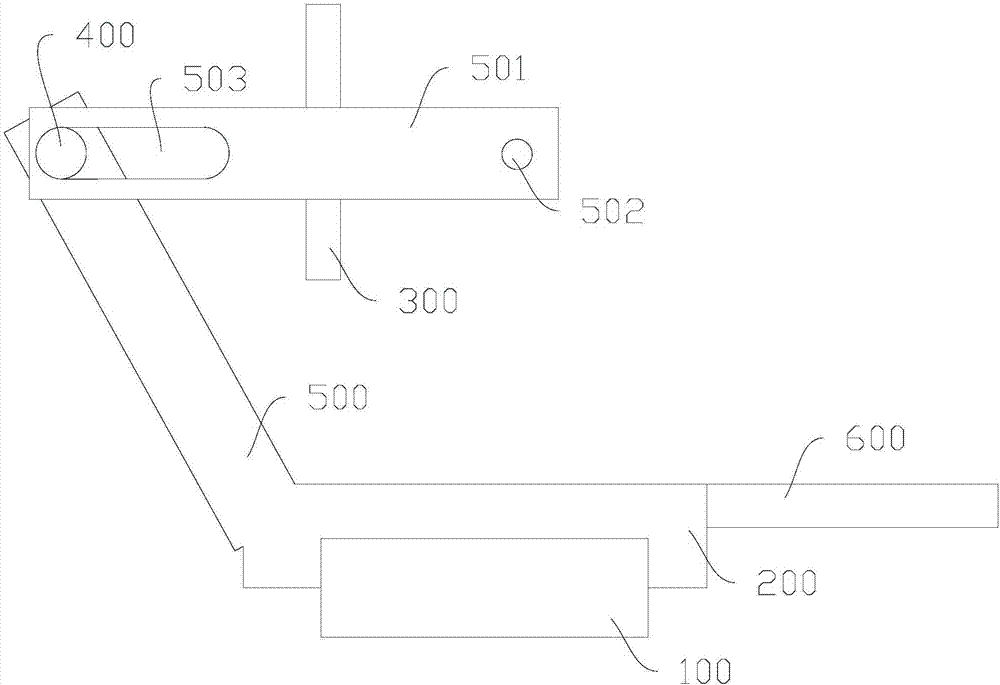
[0027] Such as figure 1 As shown, among them, other views of the cable restraint device can be obtained from the description of this application, so they are omitted. A wire arrangement constraining device for warp finishing, comprising a base 200 installed on a guide rail 100, a grid device 300 arranged above the base 200, and a crimping roller 1400; the grid device 300 is used for yarn The line passes through; the crimping roller I400 is arranged at one end connected to the connecting arm I500 of the base 200; the grid device 300 is arranged at one end connected to the connecting arm II501 of the connecting arm I500, and the connecting arm II501 is along Reverse extension of the yarn advancing direction.

[0028] Wherein, a waist-shaped through hole 503 is also provided at the junction of the connecting arm II501 and the crimping roller I400, and the crimping roller I400 is connected to the connecting arm II501 through the waist-shaped through hole 503, and the waist is Th...


PUM


Abstract

The invention relates to the weaving machinery field, and discloses a wire arrangement restraint device for warp yarn arrangement; the wire arrangement restraint device comprises a pedestal, a grid device and a compression roller I; the grid device allows yarns to pass; the compression roller I is arranged on a connecting arm I with one end connecting with the pedestal; the grid device is arranged on a connecting arm II with one end connecting with the connecting arm I; the connecting arm II extends to a direction opposite to the yarn forward direction; the connecting portion between the connecting arm II and the compression roller is also provided with a waist type through hole; the compression roller I passes the waist type through hole and is connected with the connecting arm II; the waist type through hole extends to the length direction of the connecting arm II; the connecting arm I is in an arc shape and extends along an arc curve; the pedestal also comprises a control stick. The advantages are that the wire arrangement restraint device for warp yarn arrangement can improve the yarn stability, thus providing high application values.

Description

technical field [0001] The invention relates to the field of textile machinery, in particular to a wire arrangement restraint device for warp finishing. Background technique [0002] In the process of weaving, it is necessary to arrange the yarn in advance, so that it is convenient to introduce the yarn into the weaving machine before weaving. Existing yarn finishing uses a common roller for winding. In order to remove the wound yarn from the roller more conveniently, the usual method is to wind these yarns on a pre-made On a detachable roller with a larger diameter, after the winding is completed, the roller is directly removed for the next process. Since multiple yarns are required to be carried out simultaneously during weaving, multiple yarns will be simultaneously operated correspondingly when yarns are arranged, which requires that multiple yarns can advance at a relatively stable speed, and should be Minimize the vibration of the yarn during transmission as much as ...

Claims


Application Information

Patent Timeline
Patent Type & Authority Applications(China)
IPC IPC(8): D02H3/00
CPCD02H3/00
Inventor 姚益春罗文
Owner 杭州凯秀纺织有限公司
Why Eureka
Try Eureka