Eureka AIR delivers breakthrough ideas for toughest innovation challenges, trusted by R&D personnel around the world.

Oil separator and air conditioner provided with same

An oil separator and shell technology, which can be used in household appliances, space heating and ventilation details, household heating, etc., and can solve problems such as energy consumption in heating methods

Active Publication Date: 2017-07-14
GREE ELECTRIC APPLIANCES INC
View PDF6 Cites 0 Cited by
  • Summary
  • Abstract
  • Description
  • Claims
  • Application Information

AI Technical Summary

Problems solved by technology

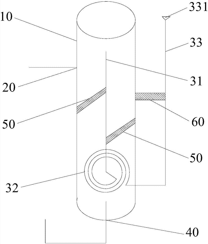
[0004] The main purpose of the present invention is to provide an oil separator and an air conditioner with it, so as to solve the problem that the heating method of the oil separator in the prior art consumes more energy

Method used


Image

  • Oil separator and air conditioner provided with same

Examples


Embodiment Construction

[0022] The following will clearly and completely describe the technical solutions in the embodiments of the present invention with reference to the accompanying drawings in the embodiments of the present invention. Obviously, the described embodiments are only some, not all, embodiments of the present invention. The following description of at least one exemplary embodiment is merely illustrative in nature and in no way taken as limiting the invention, its application or uses. Based on the embodiments of the present invention, all other embodiments obtained by persons of ordinary skill in the art without creative efforts fall within the protection scope of the present invention.

[0023] It should be noted that the terminology used here is only for describing specific implementations, and is not intended to limit the exemplary implementations according to the present application. As used herein, unless the context clearly dictates otherwise, the singular is intended to include...


PUM


Abstract

The invention provides an oil separator and an air conditioner provided with the same. The oil separator comprises a shell provided with an inner cavity, an inlet formed in the shell, a gas exhaust pipe and an oil outlet. The gas exhaust pipe comprises a gas inlet part, a heat exchange part and a gas outlet part which are sequentially arranged. The gas inlet part and the heat exchange part are arranged in the inner cavity. The heat exchange part is located under the gas inlet part, the gas outlet part penetrates out of the shell, and gas entering from the gas inlet part is used for heating liquid in the shell through the heat exchange part and is exhausted out of the gas outlet part. The oil outlet is formed in the bottom of the shell. By adoption of the technical scheme provided by the invention, the problem that a heating mode of an oil separator in the prior art consumes much energy is effectively solved.

Description

technical field [0001] The invention relates to the technical field of air-conditioning equipment, in particular to an oil separator and an air conditioner having the same. Background technique [0002] At present, the oil return control of the compressor generally adopts the scheme of an oil return capillary to control the oil return. However, when the compressor operates at low temperature, due to the increase of lubricating oil flocs in the oil separator, the viscosity increases, which will cause the resistance of the lubricating oil to pass through the oil return capillary to increase, resulting in difficulty in oil return, return Insufficient oil will eventually lead to the lack of oil in the compressor and cause the unit to stop, and even cause damage to the compressor due to severe wear and tear. [0003] In the prior art, in order to solve the above problems, an electric heating belt is usually arranged at the bottom of the oil separator, and the lubricating oil at ...

Claims


Application Information

Patent Timeline
IPC IPC(8): F25B43/02F24F13/30
CPCF24F13/30F25B43/02Y02B30/56
Inventor 罗亚军申传涛
Owner GREE ELECTRIC APPLIANCES INC
Why Eureka
Eureka Blog
Learn More