
Two-dimensional displacement measurement device and method

A measuring device and two-dimensional displacement technology, applied in the field of laser measurement, can solve problems such as low measurement accuracy, difficult application, and difficult to measure accurately

Active Publication Date: 2017-07-14
TSINGHUA UNIV
View PDF9 Cites 9 Cited by
  • Summary
  • Abstract
  • Description
  • Claims
  • Application Information

AI Technical Summary

Problems solved by technology

However, whether it is electronic speckle interferometry or digital speckle interferometry, the displacement of the object must be greater than the size of a single speckle, and the speckle size is generally in the order of microns, so the measurement accuracy of this method can only reach 1 micron Left and right, and dynamic real-time measurement is not possible
The time series speckle method can realize dynamic measurement by taking a series of patterns in the process of object displacement, but the measurement accuracy of this method is also not high, and when the object displacement exceeds 5λ, it is difficult to measure accurately
The grating moire method requires the grating to be replicated on the surface of the object, which is difficult to apply in the case of non-contact measurement
[0004] The traditional out-of-plane displacement and in-plane displacement measurement methods have their own characteristics, but it is difficult to achieve high-resolution measurement under non-contact conditions

Method used


Image

  • Two-dimensional displacement measurement device and method
  • Two-dimensional displacement measurement device and method
  • Two-dimensional displacement measurement device and method

Examples


Embodiment 1

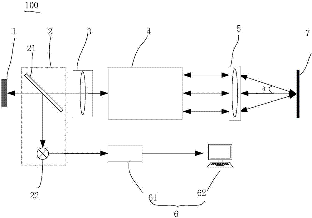
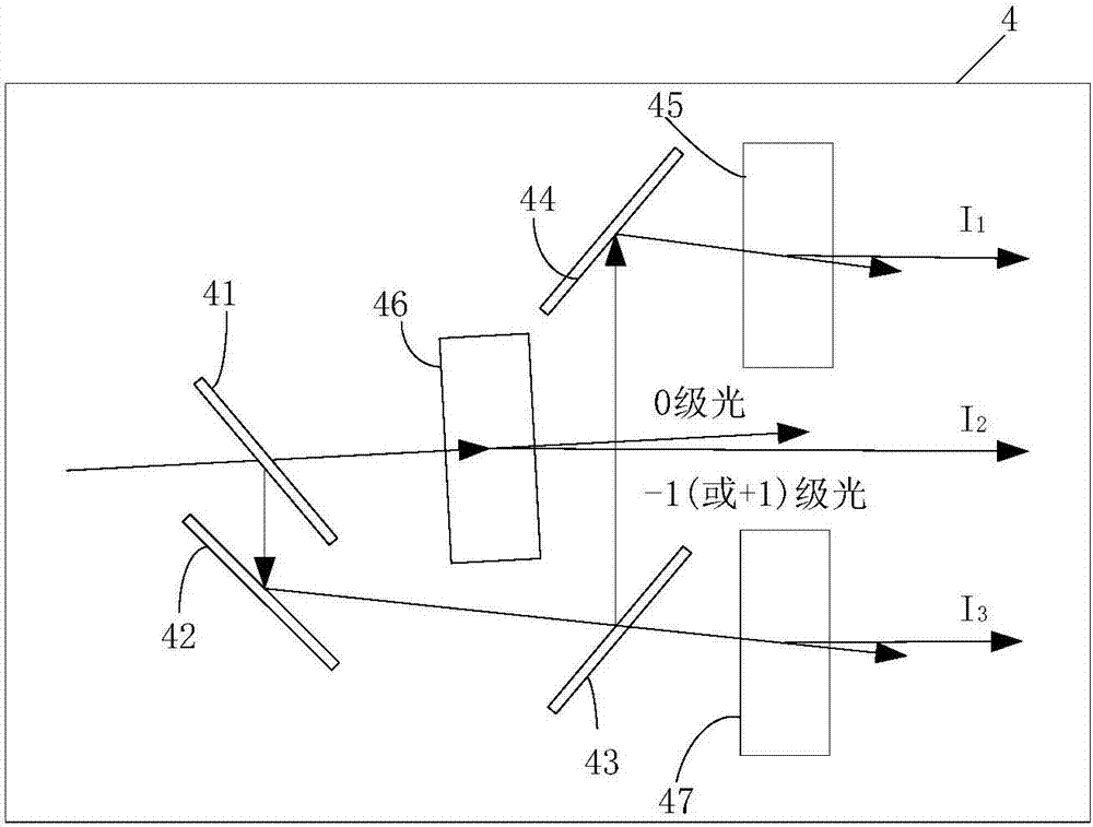
[0055] Please also refer to figure 2 In the two-dimensional displacement measurement device 100 provided by one of the embodiments of the present invention, the light splitting and frequency shifting module 4 may include a light splitting unit and a frequency shifting unit, and the light splitting unit is used to split the laser light entering the light splitting and frequency shifting module 4 to form At least three laser beams; the frequency shifting unit is used to shift the frequency of the three laser beams, and the light splitting unit cooperates with the frequency shifting unit to form at least three beams of light I 1 , I 2 , I 3 For measurement, and three beams of light I 1 , I 2 , I 3 The frequency is different.

[0056] The beam splitting unit may include a second beam splitter 41, a first mirror 42, a third beam splitter 43, and a second mirror 44; the frequency shifting unit may include a first frequency shifter 45, a second frequency shifter 46, and a secon...

Embodiment 2

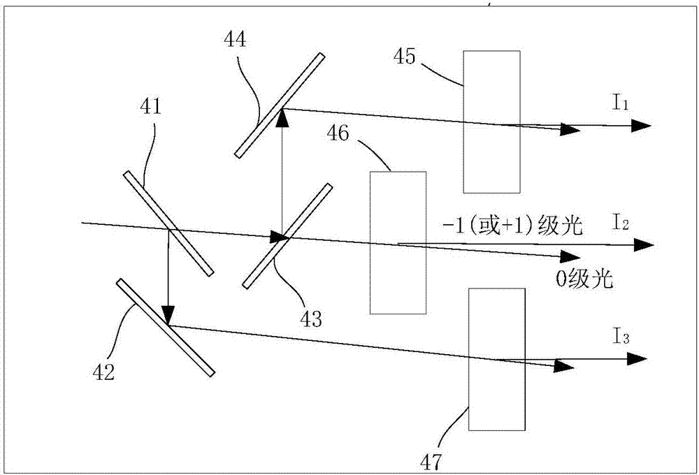
[0063] Please also refer to image 3 , the two-dimensional displacement measuring device in this embodiment is basically the same as that in Embodiment 1, the difference is that the optical frequency shifting module 4 in this embodiment is different from Embodiment 1. The light splitting and frequency shifting module 4 also includes a second beam splitter 41, a first reflector 42, a third beam splitter 43, a second reflector 44, a first frequency shifter 45, a second frequency shifter 46 and a third frequency shifter Device 47, the light splitting and frequency shifting module 4 splits the light beam entering the light splitting and frequency shifting module 4 and realizes differential frequency shifting to form three beams of light 1 1 , I 2 , I 3 For measurement, the three beams are frequency-shifted by three frequency shifters ω 1 , ω 2 and ω 3 . The optical path formed by the second beam splitter 41, the first mirror 42, the third beam splitter 43, the second mirror ...

Embodiment 3

[0068] Please also refer to Figure 4 , the two-dimensional displacement measuring device in this embodiment is basically the same as that in Embodiment 1, the difference is that the optical frequency shifting module 4 in this embodiment is different from Embodiment 1. The light splitting and frequency shifting module 4 also includes a second beam splitter 41, a first reflector 42, a third beam splitter 43, a second reflector 44, a first frequency shifter 45, a second frequency shifter 46 and a third frequency shifter Device 47, the light splitting and frequency shifting module 4 splits the light beam entering the light splitting and frequency shifting module 4 and realizes differential frequency shifting, so that the three beams of light I in the outgoing light 1 , I 2 , I 3 For measurement, the three beams are frequency-shifted by three frequency shifters ω 1 , ω 2 and ω 3 . The optical path formed by the second beam splitter 41, the first mirror 42, the third beam spl...


PUM


Abstract

The present invention relates to a two-dimensional displacement measurement device. The device comprises a laser configured to output polarization laser; a light splitting frequency shift module configured to perform light splitting of the polarization laser and realize differential frequency shift to form at least three beams of light, wherein the frequencies of the three beams of light are different; a gathering module configured to gather the at least three beams of light, allow the at least three beams of light to enter a target to be measured and receive laser returned back through scattering by the target to be measured to allow the returned laser to enter a laser to modulate the light intensity of the laser outputted by the laser; a signal detection module arranged on the optical path of the polarization laser being emergent from the laser and configured to perform detection of the light intensity of the laser outputted by the laser and convert the light intensity of the laser as electric signals; and a signal processing module connected with the signal detection module and configured to process and calculate the electric signals outputted by the signal output module and obtain out-of-plane displacement and in-plane displacement. The present invention further provides a displacement measurement method. The two-dimensional displacement measurement device and method are high in measurement precision.

Description

technical field [0001] The invention relates to a displacement measurement device and a measurement method, in particular to a two-dimensional displacement measurement and a measurement method, belonging to the field of laser measurement. Background technique [0002] The laser feedback effect is the phenomenon that in the laser system, after the output light of the laser is reflected or scattered by external objects, part of the light returns to the laser and mixes with the light in the cavity, which causes the output characteristics of the laser to change. The laser frequency shift feedback technology based on the laser feedback effect not only has the advantages of simple structure, non-contact and non-destructive testing, but also has the characteristics of high sensitivity and can measure rough surfaces. At present, laser feedback technology has been applied in precision displacement measurement, velocity measurement, shape measurement, vibration measurement, phase dela...

Claims


Application Information

Patent Timeline
Patent Type & Authority Applications(China)
IPC IPC(8): G01B11/02
Inventor 谈宜东郭波朱开毅卢悦越张书练
Owner TSINGHUA UNIV
Learn More