Antenna and mobile terminal

An antenna, antenna radiation technology, applied in the direction of antenna, antenna grounding switch structure connection, antenna equipment with additional functions, etc., can solve the problems of poor antenna bandwidth and efficiency

Active Publication Date: 2017-07-14
VIVO MOBILE COMM CO LTD
View PDF6 Cites 13 Cited by
  • Summary
  • Abstract
  • Description
  • Claims
  • Application Information

AI Technical Summary

Problems solved by technology

[0003] An embodiment of the present invention provides an antenna to solve the problem in the prior art that different radiation modes of the antenna share a matching circuit so that the bandwidth and efficiency of the antenna are poor
[0004] The embodimen

Method used


Image

  • Antenna and mobile terminal
  • Antenna and mobile terminal
  • Antenna and mobile terminal

Examples


no. 1 example

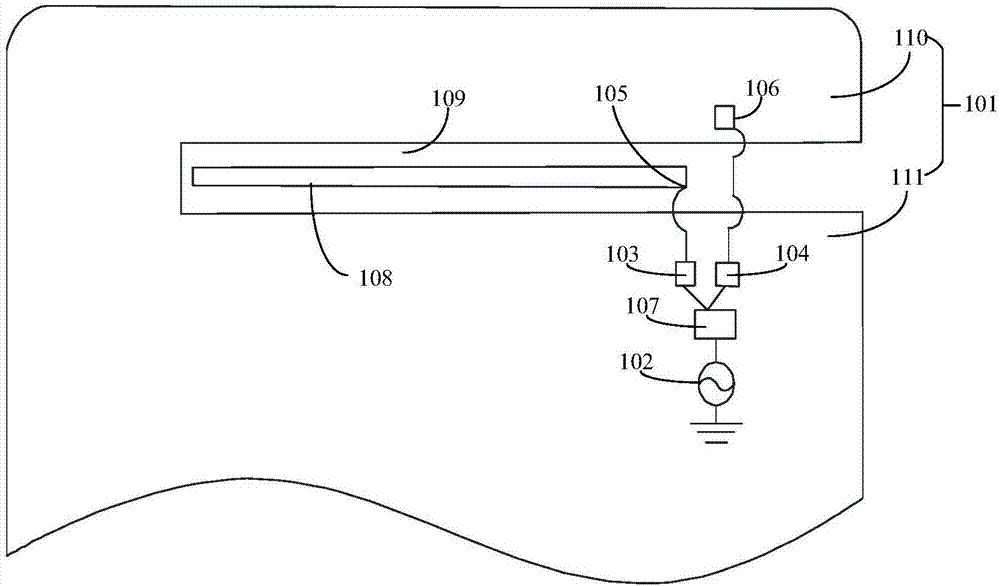
[0029] The first embodiment of the present invention discloses an antenna. Such as figure 1 As shown, the antenna includes: a metal shell 101 , a feed source 102 , a low frequency matching circuit 103 , a high frequency matching circuit 104 , a low frequency feed point 105 , a high frequency feed point 106 , an antenna switch 107 and a coupling piece 108 .

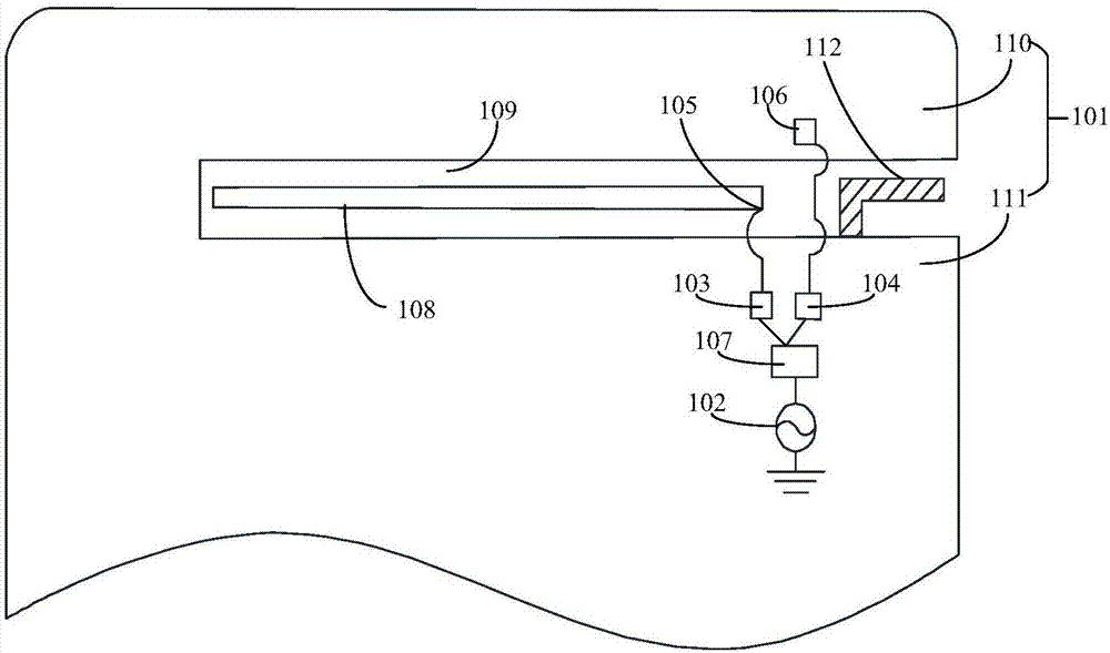
[0030] A slot 109 is disposed on the metal shell 101 . The gap 109 divides the metal shell into an antenna radiation arm 110 and a main reference ground 111 . One side of the metal shell 101 has a fracture, and the gap 109 communicates with the fracture. The coupling piece 108 is disposed in the slot 109 . The coupling piece 108 is generally a long strip of sheet metal. It should be understood that the shape of the coupling piece 108 is not limited thereto, and may also be an irregular sheet metal. The coupling piece 108 can be flush with the slit 109 or have a certain height difference in the height direction. One e...

no. 2 example

[0038] The second embodiment of the present invention discloses an antenna. Such as Image 6 As shown, the antenna includes: a metal shell 601 , a first feed 602 , a second feed 607 , a low frequency matching circuit 603 , a high frequency matching circuit 604 , a low frequency feed 605 , a high frequency feed 606 and a coupling piece 608 .

[0039] A gap 609 is provided on the metal shell 601 . The gap 609 divides the metal shell into an antenna radiation arm 610 and a main reference ground 611 . One side of the metal shell 601 has a fracture, and the gap 609 communicates with the fracture. The coupling piece 608 is disposed in the slot 609 . The coupling piece 608 is generally a long strip of sheet metal. It should be understood that the shape of the coupling piece 608 is not limited thereto, and may also be an irregular sheet metal. The coupling piece 608 may be flush with the slit 609 or have a certain height difference in the height direction. One end of the first f...

no. 3 example

[0047] The third embodiment of the present invention discloses an antenna. Such as Figure 9 As shown, the antenna includes: a metal shell 901 , a feed source 902 , a low frequency matching circuit 903 , a high frequency matching circuit 904 , a low frequency feed point 905 , a high frequency feed point 906 and an antenna switch 907 .

[0048] The metal shell 901 is provided with a slit 909 . The gap 909 divides the metal shell into an antenna radiation arm 910 and a main reference ground 911 . One side of the metal shell 901 has a fracture, and the gap 909 communicates with the fracture. One end of the feed 902 is grounded. The input end of the antenna switch 907 is connected to the other end of the feed source 902 . The first output end of the antenna switch 907 is connected to one end of the low frequency matching circuit 903 . The second output end of the antenna switch 907 is connected to one end of the high frequency matching circuit 904 . Specifically, the antenna...


PUM


Abstract

The embodiment of the invention provides an antenna which comprises a metal shell and at least one feed source. The antenna further comprises a low-frequency matching circuit, a high-frequency matching circuit, a low-frequency feed point and a high-frequency feed point; a gap is formed on the metal shell, the gap divides the metal shell into an antenna radiation arm and main reference ground, one side edge of the metal shell is provided with a fracture, and the gap is communicated with the fracture; one end of the low-frequency matching circuit is connected with the other end of the feed source, the other end of the low-frequency matching circuit is connected with the low-frequency feed point, and the low-frequency feed point is positioned in the gap or at the position of the antenna radiation arm; and one end of the high-frequency matching circuit is connected with the other end of the feed source, the other end of the high-frequency matching circuit is connected with the high-frequency feed point, and the high-frequency feed point is positioned at the position of the antenna radiation arm. By separating the low-frequency matching circuit and the high-frequency matching circuit of the antenna excellent antenna performance in a wide frequency band can be achieved, and the antenna is excellent in both bandwidth and efficiency.

Description

technical field [0001] The present invention relates to the technical field of antennas, in particular to an antenna and a mobile terminal. Background technique [0002] The wide-band antenna of the metal body of the existing mobile terminal includes a slot and a feed source. Among them, the low-frequency radiation mode and the high-frequency radiation mode are switched by switching the effective length of the slot (that is, the antenna radiator path length). Therefore, the adjustable range of the matching circuit in the prior art is limited, and the matching method is limited by different radiation modes. , therefore, different radiation modes need to share the matching circuit, making the bandwidth and efficiency of the antenna poor. Contents of the invention [0003] An embodiment of the present invention provides an antenna to solve the problem in the prior art that different radiation modes of the antenna share a matching circuit so that the bandwidth and efficiency ...

Claims


Application Information

Patent Timeline
IPC IPC(8): H01Q5/50H01Q5/335H01Q1/50H01Q1/44
CPCH01Q1/44H01Q1/50H01Q5/335H01Q5/50
Inventor 侯梓鹏
Owner VIVO MOBILE COMM CO LTD
Why Eureka
Try Eureka