Automobile pipe port forming equipment and port forking method thereof

A technology for forming equipment and pipe fittings, applied in forming tools, metal processing equipment, manufacturing tools, etc., can solve the problems of high cost and low efficiency, and achieve the effect of high processing efficiency, low labor cost and good forming stability

Active Publication Date: 2017-07-18
宁波嘉天汽车管件有限公司
View PDF8 Cites 6 Cited by
  • Summary
  • Abstract
  • Description
  • Claims
  • Application Information

AI Technical Summary

Problems solved by technology

[0003] The purpose of the present invention is to solve the defects of low efficiency and high cost in the pipe end forming process of existing automobile pipe fittings, and to provide a simple structure, high production efficiency and low cost automobile pipe fitting end forming equipment and its end forming method

Method used


Image

  • Automobile pipe port forming equipment and port forking method thereof
  • Automobile pipe port forming equipment and port forking method thereof
  • Automobile pipe port forming equipment and port forking method thereof

Examples


Embodiment 1

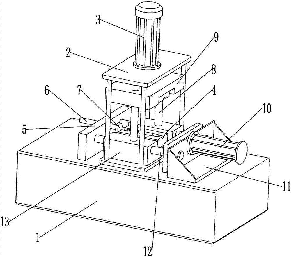
[0036] The automobile pipe fitting port forming equipment disclosed in this embodiment, such as image 3 As shown, it includes a frame 1, a mold frame 2, a forming mold 4 and a pressing mechanism, the mold frame 2 is fixedly installed on the frame 1, the mold frame 2 is provided with a mold installation cavity, and the forming mold 4 is installed in the mold installation cavity, The pressing mechanism is arranged on the side of the molding die 4 .

[0037] Such as image 3 with Figure 5 As shown, the formwork 2 includes an upper mounting plate 21, a lower mounting plate 23, and four columns 22 corresponding to the upper and lower spacing distances. The lower mounting plate 23 is fixedly installed on the top of the frame 1, and the four columns 22 are vertically distributed on the lower mounting plate. The surroundings and the bottom end of the plate 23 pass through the lower mounting plate 23 and are fixedly connected with the frame 1. The upper mounting plate 21 is fixedly i...

Embodiment 2

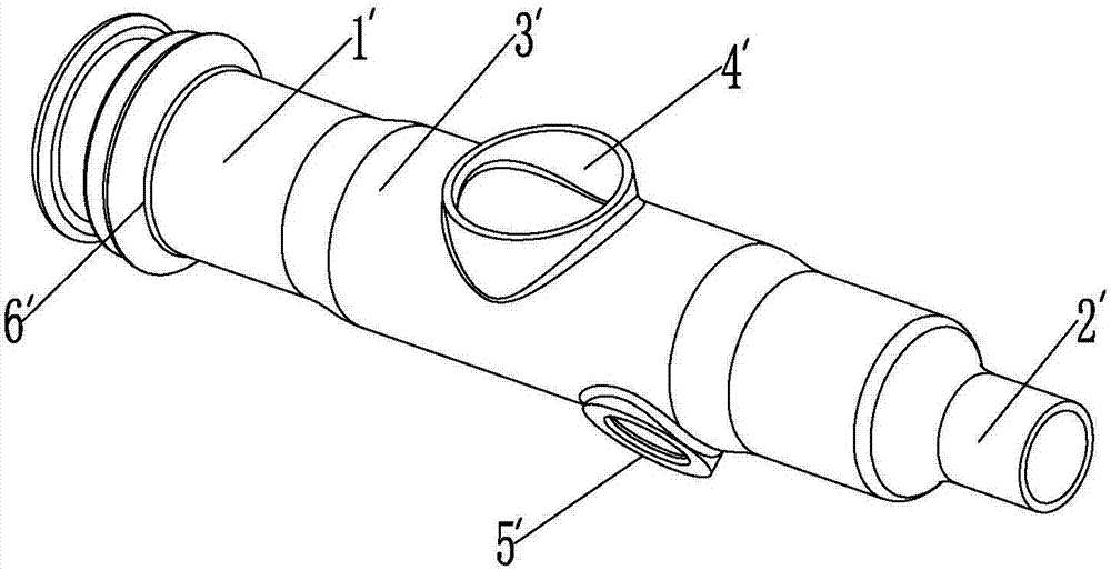
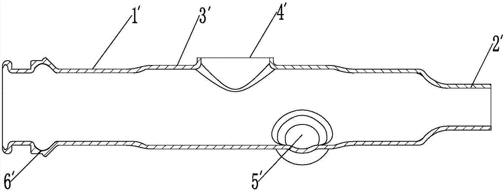
[0041] Embodiment two, automobile pipe fitting port forming method, such as image 3 , Figure 5 with Figure 8 As shown, insert the mandrel into the automobile pipe fitting to be formed, make the small diameter section of the stepped shaft 17 protrude from the necking section of the automobile pipe fitting to be formed, and the bulging block 18 is located in the inner cavity corresponding to the forming end of the pipe fitting to be formed, and then Place the pipe fittings to be formed into the lower mold cavity of the lower mold 42, and the lifting drive mechanism drives the upper mold 41 to move downward until the upper mold 41 and the lower mold 42 are combined to fill the automobile pipe fittings in the mold cavity and press them tightly to fix them. The jacking block 7 leans against the end of the molding die corresponding to the forming end of the pipe fitting, the movable jacking block 16 leans against the end of the small diameter section of the stepped shaft 17, and...


PUM


Abstract

The invention discloses automobile pipe port forming equipment and a port forking method thereof. The key point of the technical scheme is that the automobile pipe port forming equipment comprises a rack, a die frame, a forming die and a top pressure mechanism, wherein the die frame is fixedly mounted on the rack; a die mounting cavity for mounting the forming die is formed in the die frame; the forming die comprises an upper die and a lower die which are correspondingly arranged up and down, a lifting driving mechanism for driving the upper die to do lifting motion and a mandrel; the mandrel comprises a bulging block and a step shaft; the diameter of a small-diameter section of the step shaft is less than the inner diameter of a reducing section of an automobile pipe; the diameter of a large-diameter section of the step shaft corresponds to the inner diameter of a pipe body of the automobile pipe; the bulging block is a cylinder; one end of the bulging block is fixedly connected with the end surface of the large-diameter section of the mandrel; and the top pressure mechanism comprises a fixed ejector block and a movable ejector block which are relatively arranged at two ends of a die cavity of the forming die, and a top pressure driving assembly for driving the movable ejector block to do relative motion to the fixed ejector block. The problems of low efficiency and relatively high cost of the existing automobile pipe during pipe end forming machining are solved.

Description

technical field [0001] The invention relates to the technical field of pipe fitting forming, in particular to an automobile pipe fitting port forming equipment and a port forming method thereof. Background technique [0002] There are many interconnected pipes on the car. In order to facilitate the connection and the firmness and sealing of the joints, some pipes are often provided with radially outwardly protruding ribs and shrinkage near the connection port. For example, the high-pressure air pipe on a car has a structure such as figure 1 with figure 2 As shown, including the pipe fitting body 1', one end of the pipe fitting body 1' is provided with a necking section 2', and the middle part of the pipe fitting body 1' is provided with a connecting section 3' whose outer diameter is larger than that of the pipe fitting body. There is an elbow connection opening 4' and a small hole connection port 5', and the other end of the pipe fitting body 1' near the port is provided...

Claims


Application Information

Patent Timeline
IPC IPC(8): B21D41/02B21D41/04B21D37/10
CPCB21D37/10B21D41/028B21D41/04
Inventor 张力天
Owner 宁波嘉天汽车管件有限公司
Why Eureka
Try Eureka