Method for machining positioning welding clamp

A positioning welding and fixture technology, applied in the field of mechanical processing, can solve problems such as poor welding and high positioning structure requirements, and achieve the effect of ensuring tolerance requirements

Active Publication Date: 2017-07-18
SHENYANG AIRCRAFT CORP
View PDF5 Cites 3 Cited by
  • Summary
  • Abstract
  • Description
  • Claims
  • Application Information

AI Technical Summary

Problems solved by technology

At this time, in order to ensure the welding quality, manual assistance is required. If the cooperation between the personnel is not tacit, it may also lead to poor welding.
Especially for the welding of the elbow structure, there are still many problems at this stage. The state of the elbow structure after welding has higher requirements for the positioning structure of this type of positioning welding tool.

Method used


Image

  • Method for machining positioning welding clamp
  • Method for machining positioning welding clamp
  • Method for machining positioning welding clamp

Examples


Embodiment Construction

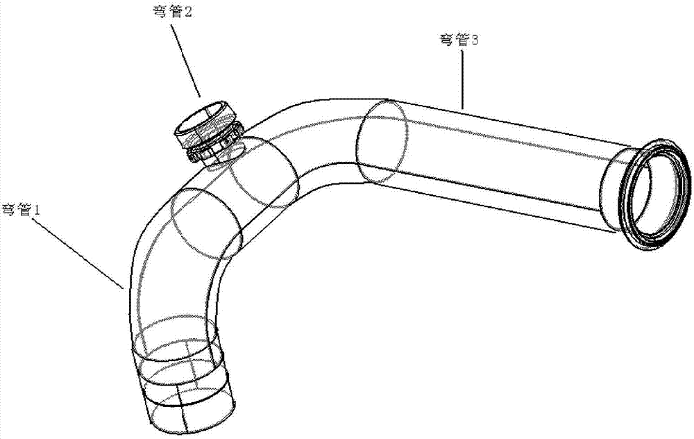
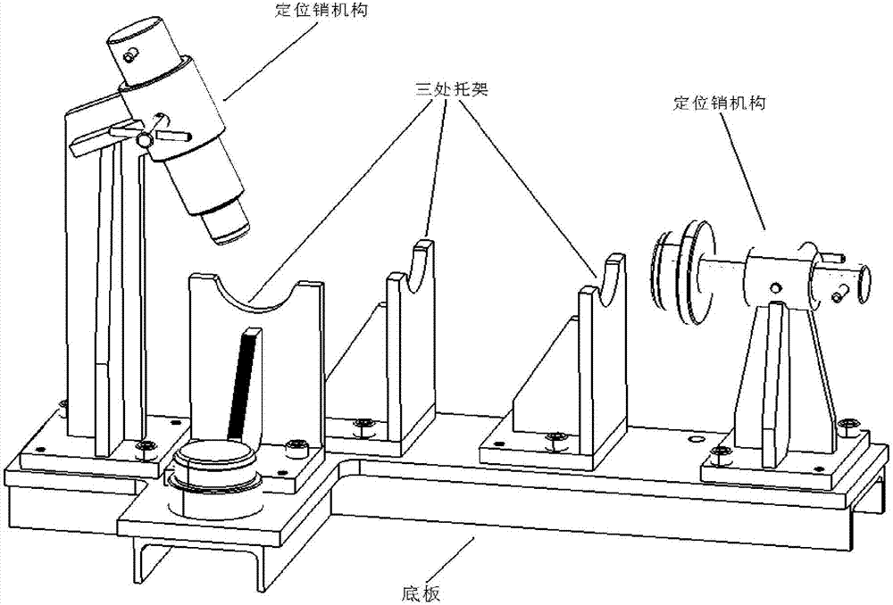
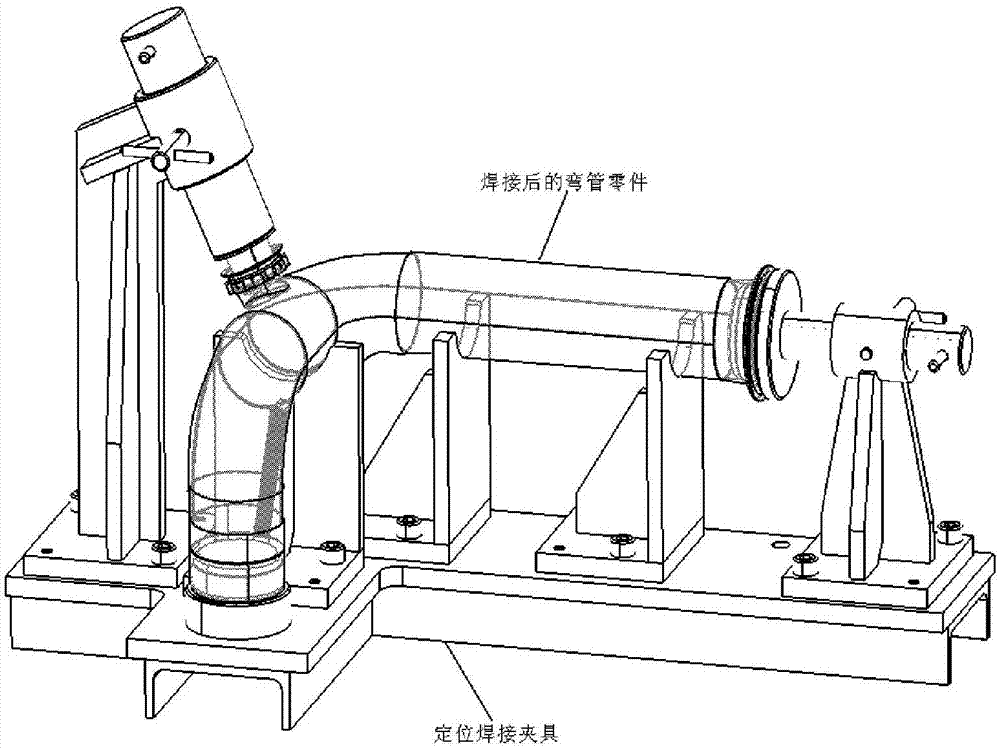
[0025] figure 1 This is a schematic diagram of this type of elbow after welding, which is welded by three elbow parts. figure 2 For the schematic diagram of this kind of positioning welding fixture, this tooling is designed with three brackets and two positioning pin mechanisms, which are used to position three elbow parts to ensure the welding position requirements. image 3 An overall schematic diagram for positioning the welding fixture and welding parts. A positioning welding jig processing device includes three brackets, two positioning pins, and a bottom plate; the brackets and positioning pin mechanisms are all welded structures, and are used for positioning welding parts to ensure welding position requirements. The two positioning pins are fixedly installed on the left and right ends of the bottom plate, and the three brackets are respectively fixedly installed on the top of the bottom plate.

[0026] The following is the specific processing plan for the welding too...


PUM


Abstract

The invention belongs to the field of machining, and provides a method for machining a positioning welding clamp. The machining method includes the steps that firstly, a bottom plate used for connecting three brackets and two positioning pin mechanisms is machined, and position lines of the brackets and the positioning pin mechanisms are drawn through a numerically-controlled needle; secondly, after single-piece machining and welding are conducted on the brackets and the positioning pin mechanisms, internal force is removed through annealing, the bottom faces of the brackets and the positioning pin mechanisms are milled to be flat through a milling machine, and it is ensured that the brackets and the positioning pin mechanisms are attached to the bottom plate; and thirdly, the whole bottom plate, the whole brackets and the whole positioning pin mechanisms are machined, the bottom plate, the brackets and the positioning pin mechanisms are measured to be qualified after numerically-controlled machining, and inspection is conducted after bench workers polish numerically-controlled machining moulding faces. The machining method has the beneficial effects that due to the adoption of the machining method, the relative position relationship of the three brackets and the positioning pin mechanisms can be ensured, and the tolerance requirement of the positioning and welding clamp can be ensured.

Description

technical field [0001] The invention belongs to the field of mechanical processing, and relates to a processing method of a positioning welding fixture for welding bent pipe parts. The positioning welding fixture is used for welding several formed bent pipe parts into an integral bent pipe part. Background technique [0002] During the welding process, it is necessary to use a jig to position the welded part. Although the existing welding jig can position the workpiece to be welded, there is still the problem of inaccurate welding. In the existing welding clamp, in order to facilitate the workpiece to be welded to be placed in the positioning area better, there will be a gap between the welding fixture and the workpiece to be welded, and these reserved gaps will make the gap between the workpiece to be welded and the workpiece to be welded It is not tightly attached to the welding fixture. At this time, in order to ensure the welding quality, manual assistance is required. ...

Claims


Application Information

Patent Timeline
IPC IPC(8): B23P15/00B23K37/04
CPCB23K37/0435B23P15/00
Inventor 周通
Owner SHENYANG AIRCRAFT CORP
Why Eureka
Try Eureka