A Gravity Deformation Compensation Device for Optical Elements

A technology of gravitational deformation and optical elements, which is applied in the direction of photolithography process exposure devices, microlithography exposure equipment, etc., can solve the problems affecting the imaging quality of the optical system, and achieve the effect of reducing the difficulty of structural design, saving space, and reducing coupling

Inactive Publication Date: 2017-05-31
CHANGCHUN INST OF OPTICS FINE MECHANICS & PHYSICS CHINESE ACAD OF SCI
View PDF5 Cites 0 Cited by
  • Summary
  • Abstract
  • Description
  • Claims
  • Application Information

AI Technical Summary

Problems solved by technology

However, in a high-precision optical system such as a 193nm lithography projection objective lens, the maximum diameter of the lens reaches 300mm, and the error of a single lens caused by gravity deformation can reach tens of nanometers, which will seriously affect the imaging quality of the optical system

Method used


Image

  • A Gravity Deformation Compensation Device for Optical Elements
  • A Gravity Deformation Compensation Device for Optical Elements
  • A Gravity Deformation Compensation Device for Optical Elements

Examples


Embodiment Construction

[0030] The present invention will be further explained with specific embodiments below, but it is not intended to limit the protection scope of the present invention.

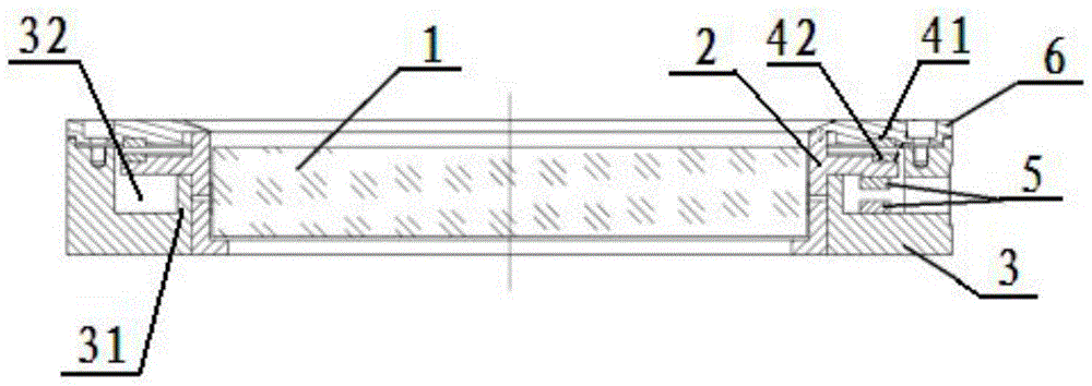
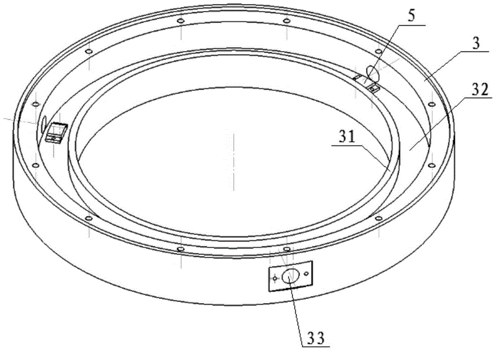
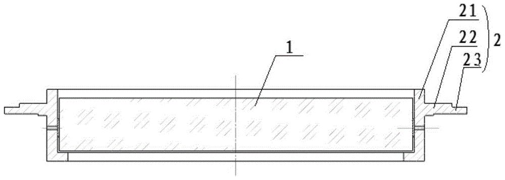
[0031] In order to compensate the rotationally symmetric aberrations introduced by the gravity due to the high-precision support of the optical elements in the lithographic projection objective lens, the rotationally symmetric aberrations are mainly Power terms and spherical aberrations, see figure 1 , the present embodiment provides a kind of gravitational deformation compensation device for optical elements, including: outer mirror frame 3, deformable mirror frame 2, upper cover plate 6, first annular electromagnet 41 and second annular electromagnet 42, see figure 2 , an upwardly extending support platform 31 is provided on the inner periphery of the outer mirror frame 3, and the width of the support platform 31 is about 3-5mm. The blue interface presses the deformable mirror frame 2 into the outer mirror f...


PUM


Abstract

The invention discloses an optical element gravity deformation compensating device, which comprises an optical element, a deformable mirror frame, a pair of annular electromagnets, a capacitive sensor and an upper cover plate; the deformable mirror frame is composed of a mirror frame inner ring, a mirror frame outer ring and a supporting ring The integrated structure of the mirror frame, the inner ring of the frame is fixedly connected with the optical element through the glue injection hole on the side wall, the lower part of the supporting ring is in contact with the boss of the outer mirror frame to provide a support point, and a ring electromagnet is installed on the upper part of the outer ring of the mirror frame. The repulsion provides a vertical downward displacement. After loading, the outer frame of the deformable mirror frame drives the inner frame to move axially, which causes the optical element to deform, and finally realizes the compensation of rotationally symmetrical aberrations; it has the advantages of simple structure and reasonable design.

Description

technical field [0001] The invention relates to high-precision optical element support structure design and surface shape compensation, and in particular provides an optical element gravity deformation compensation device. Background technique [0002] For the manufacturing process of large-scale integrated circuits, projection lithography is the most critical process, and a projection lithography machine is required. The projection objective lens is the core of the projection lithography machine, and its performance directly determines the lithography line. resolution. [0003] In order to ensure the extremely high imaging quality of the projection objective lens, the surface shape accuracy of each surface of the optical element after processing and coating is only allowed to be λ / 100, which is about 1nm~2nm (RMS). Generally speaking, in the visible waveband, when the optical lens diameter is small (Ф<100mm), the deformation caused by the lens's own weight is about λ / 20...

Claims


Application Information

Patent Timeline
Patent Type & Authority Patents(China)
IPC IPC(8): G03F7/20
Inventor 方斌田伟苗二龙
Owner CHANGCHUN INST OF OPTICS FINE MECHANICS & PHYSICS CHINESE ACAD OF SCI
Why Eureka
Try Eureka