Two-part supporting type flange connecting structure and designing method thereof

A connection structure, support technology, applied in design optimization/simulation, calculation, mechanical equipment, etc., can solve the problems of reduced bolt safety margin, increased weight of flange connection structure, low bolt safety margin, etc., to increase the strength The effect of margin, weight reduction, and bending moment reduction

Active Publication Date: 2017-07-18
BEIJING AEROSPACE PROPULSION INST
View PDF5 Cites 10 Cited by
  • Summary
  • Abstract
  • Description
  • Claims
  • Application Information

AI Technical Summary

Problems solved by technology

The action of bending moment will make the stress distribution of the bolt along its circumferential direction uneven. Under the condition of the same axial force, the uneven stress distribution will cause the peak value of the stress to increase and the safety margin of the bolt will decrease.
For the single-position supported flange connection structure, the bolts are subject to a large bending moment in the assembled state, and the bending moment on the bolts will further increase in the working state. Under the same axial force of the bolts, The safety margin of the bolt is low
[0004] In order to reduce the bending moment on the bolts, the method of increasing the thickness of the flange is generally used to increase the stiffness of the flange, which leads to an increase in the weight of the flange connection structure

Method used


Image

  • Two-part supporting type flange connecting structure and designing method thereof
  • Two-part supporting type flange connecting structure and designing method thereof
  • Two-part supporting type flange connecting structure and designing method thereof

Examples


Embodiment

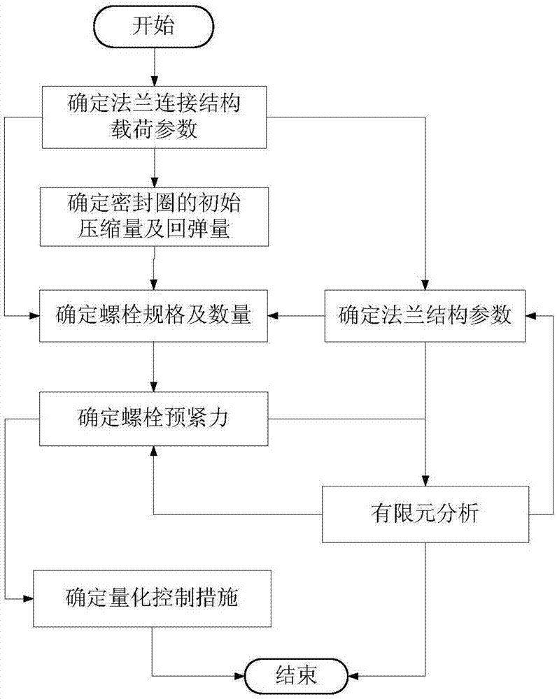
[0053] The structural characteristics and design process of the two-part support flange are described below through specific examples:

[0054] (1) The diameter of the flange is 120mm, and the internal pressure of the medium is 40MPa, so the axial separation force F of the flange connection structure is calculated 1 =Pπr 2 =452.4kN.

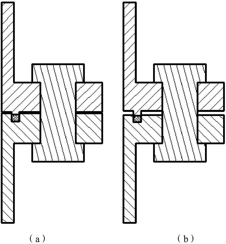
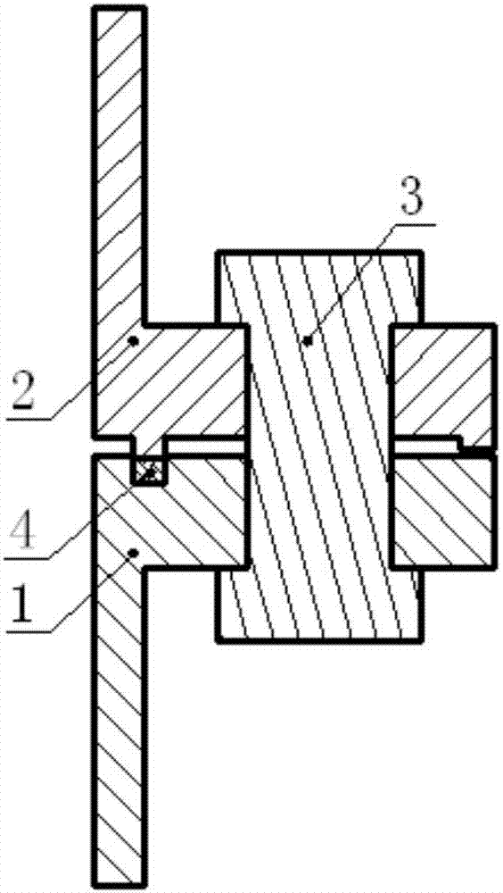
[0055] (2) Assuming that the sealing ring 4 is an elastic structure with a stiffness of 100kN / mm, according to the leakage rate requirement, the initial compression of the sealing ring 4 is a=1.0mm, and the maximum allowable springback is b max = 0.3mm; then when the first flange 1 and the second flange 2 are just in contact with the sealing ring 4, the initial value of the gap between the raised structure at the outer edge of the second flange 2 and the first flange 1 is c 0 =a-b max =0.7mm; assuming that the depth of the sealing groove of the first flange 1 is 4.2mm, the height of the sealing tenon of the second flange 2 is 1.9mm, and the he...


PUM


Abstract

The invention discloses a two-part supporting type flange connecting structure which is a flange connecting structure capable of decreasing the bolt peak stress and increasing the bolt strength allowance. The designing process of the flange connecting structure comprises the following steps that firstly, the compression amount and the springback amount of a seal ring are determined according to the sealing requirements or relevant standards, and then the height difference between two supporting parts is calculated; secondly, the number and specification of bolts are primarily determined according to separating force borne by a flange and the drift diameter of the flange; thirdly, the flange shape can be primarily determined by experience, and parameters such as the flange shape, the bolt specification and the pretightening force are optimized by conducting finite element analysis; lastly, the bolt pretightening force is converted into a control parameter for engineering use. According to the two-part supporting type flange connecting structure, bending moment peak values borne by the bolts in the whole working cycle can be effectively decreased, then a bolt stress peak value is decreased, the strength safety allowance of the bolts is increased, then the flange stiffness requirements are lowered, and the overall weight of the flange connecting structure is decreased.

Description

technical field [0001] The invention relates to a flange connection structure and a design method thereof. Background technique [0002] The rocket engine has strict requirements on the structural weight, and the reduction of the structural weight of the engine means the increase of the payload weight of the rocket. A large number of liquid rocket engines use flange connection structures. According to the different supporting parts of the two flanges, the current flange connection structures can be roughly divided into two categories: 1) Large-area contact flange connection structures, such as figure 1 As shown in (a); 2) Only the sealing structure is in contact - a single position supporting flange connection structure, such as figure 1 (b) shown. [0003] The sealing ring is located on the medium side. For the large-area contact flange connection structure, the bolts are basically not subject to bending moments in the assembled state (not filled with medium) (due to the ...

Claims


Application Information

Patent Timeline
Patent Type & Authority Applications(China)
IPC IPC(8): F02K9/60G06F17/50
CPCF02K9/60G06F30/17G06F30/23
Inventor 朱景文吴洋洲曾诚王新军杨正黄志亮樊仕营赵哲王志云常红韩放贾傲孙彦铭
Owner BEIJING AEROSPACE PROPULSION INST
Why Eureka
Try Eureka