Small-sized intersecting and bending omnidirectional ultra-wideband antenna

An ultra-wideband antenna and bending technology, which is applied in the direction of antenna grounding switch structure connection, radiation element structure, etc., can solve the problems that ultra-wideband antennas cannot achieve omnidirectional radiation and large cross-sectional area

Inactive Publication Date: 2017-07-18
HARBIN INST OF TECH
View PDF3 Cites 0 Cited by
  • Summary
  • Abstract
  • Description
  • Claims
  • Application Information

AI Technical Summary

Problems solved by technology

[0004] The purpose of the present invention is to solve the problem that the existing miniaturized ultra-wideband antenna cannot realize o

Method used


Image

  • Small-sized intersecting and bending omnidirectional ultra-wideband antenna
  • Small-sized intersecting and bending omnidirectional ultra-wideband antenna
  • Small-sized intersecting and bending omnidirectional ultra-wideband antenna

Examples


specific Embodiment approach 1

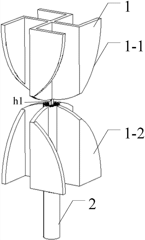
[0029] Specific implementation mode one: combine figure 1 with figure 2 Describe this embodiment in detail. A small cross-bending omnidirectional ultra-wideband antenna described in this embodiment includes 4 half-circles 1 and 1 coaxial cable 2;

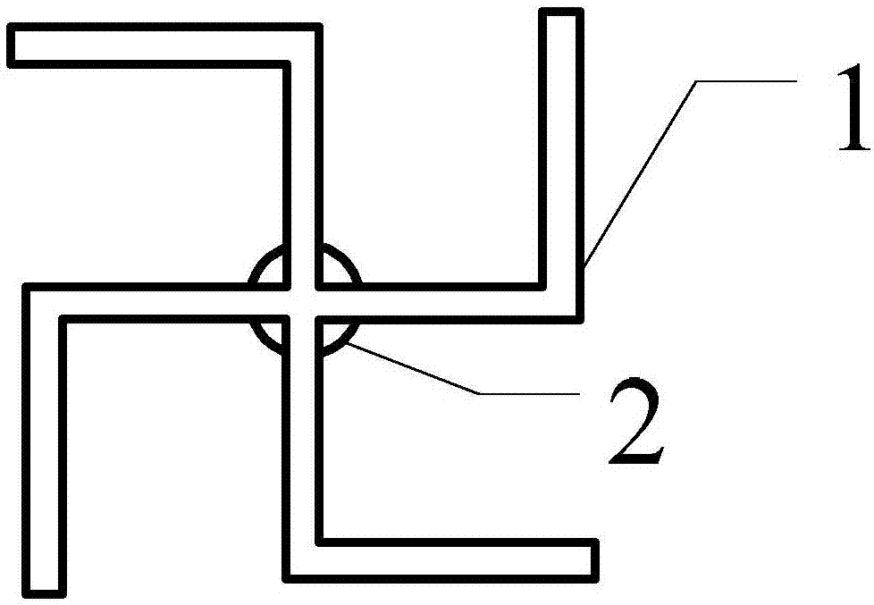
[0030] The radii of the four semi-circles 1 are the same, and the semi-circles 1 are crossed vertically in pairs to form two dipoles, which are dipole one 1-1 and dipole two 1-2, and the coaxial line 2 is located on the semi-circle 1 The center line of the coaxial line 2 passes through dipole two 1-2 and connects with dipole one 1-1. The arc parts of the two dipoles are opposite, and the distance between the tops of the two dipole arcs is h1 , each semicircle 1 is bent 90° counterclockwise at r / 2 of the left and right sides of the straight edge, h1 is a positive number, and r is the radius of the semicircle 1 .

[0031] A miniaturized omnidirectional UWB antenna is designed, simulated and tested by means of crossing and bending. ...

specific Embodiment approach 2

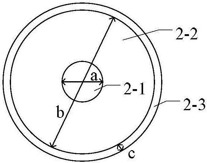
[0032] Specific implementation mode two: combination image 3 Describe this embodiment in detail. This embodiment is a further description of a small cross-bending omnidirectional ultra-wideband antenna described in Embodiment 1. In this embodiment, the coaxial line 2 includes an inner core 2-1 , medium layer 2-2 and skin 2-3;

[0033] The inner core 2-1 is covered with a dielectric layer 2-2, and the dielectric layer 2-2 is covered with a skin 2-3; the coaxial line 2 in contact with the dipole 1-1 is stripped of the dielectric layer 2-2 and the skin 2-3.

specific Embodiment approach 3

[0034] Specific embodiment three: This embodiment is a further description of a small cross-bending omnidirectional ultra-wideband antenna described in specific embodiment two. In this embodiment, the diameter a of the inner core 2-1 is 0.9mm , the diameter b of the dielectric layer 2-2 is 3.2mm, the relative dielectric constant εr of the medium is 2.43, and the thickness c of the outer skin 2-3 is 0.1mm.


PUM

PropertyMeasurementUnit
Diameteraaaaaaaaaa
Diameteraaaaaaaaaa
Thicknessaaaaaaaaaa

Abstract

A small-sized intersecting and bending omnidirectional ultra-wideband antenna is disclosed and is used for solving a problem that a conventional small-sized ultra-wideband antenna cannot realize omnidirectional radiation and is large in cross-sectional area. Four semicircle sheets are the same in radius and intersect with each other vertically in pairs, two dipoles that are respectively a first dipole and a second dipole are formed, a coaxial line is positioned on center lines of the semicircle sheets, the coaxial line is connected with the first dipole after running through the second dipole, arc parts of the two dipoles are arranged in a face to face manner, top ends of arcs of the two dipoles are h1 from each other, each semicircle sheet is bent 90 degrees in an anticlockwise direction at r/2 from a left side and a right side of a straight line, and r is radius of the semicircle sheet. The small-sized intersecting and bending omnidirectional ultra-wideband antenna is suitable for occasions where omnidirectional ultra-wideband antennas are applied.

Description

technical field [0001] The invention relates to a cross-bending omnidirectional ultra-wideband antenna. Background technique [0002] In recent years, with the development of science and technology and the advent of the information age, ultra-wideband communication technology has developed rapidly, and it has the ability of ultra-wideband connection with radio equipment in a small range. With the application of ultra-wideband technology more and more widely, miniaturized omnidirectional ultra-wideband antenna has become a research hotspot. The study of omnidirectional ultra-wideband antennas has broad application prospects and important practical significance in both civil and military applications. [0003] However, the existing miniaturized ultra-broadband antenna cannot realize omnidirectional radiation, and has a large lateral area, requiring a large installation space. Contents of the invention [0004] The purpose of the present invention is to solve the problem th...

Claims


Application Information

Patent Timeline
IPC IPC(8): H01Q1/36H01Q1/50
Inventor 李伟索莹徐晓鹏刘艳王洪永
Owner HARBIN INST OF TECH
Why Eureka
Try Eureka