Meat protein production line for feed

A meat protein and production line technology, which is applied in the field of feed meat protein production line, can solve the problems of unsuitable production technology and achieve the effect of safe and high-quality feed

Active Publication Date: 2019-09-24
北京中科昊盈生物技术有限公司
View PDF6 Cites 0 Cited by
  • Summary
  • Abstract
  • Description
  • Claims
  • Application Information

AI Technical Summary

Problems solved by technology

However, when the raw materials used are different, the technological process used should also be adjusted accordingly. When oil residue is used as raw material, the production process of the prior art is not suitable

Method used


Image

  • Meat protein production line for feed
  • Meat protein production line for feed
  • Meat protein production line for feed

Examples


Embodiment 1

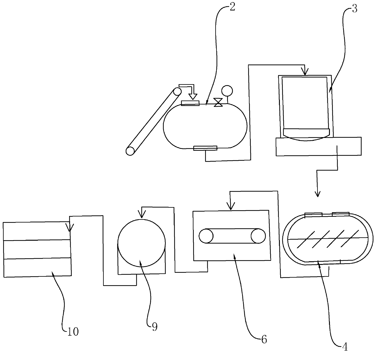
[0046] Such as figure 1 As shown, a meat protein production line for feed is characterized in that it includes a cooking tank 2, an oil press 3, a dryer, a cooler 6, a pulverizer 9 and a rotary screen 10 connected in sequence.

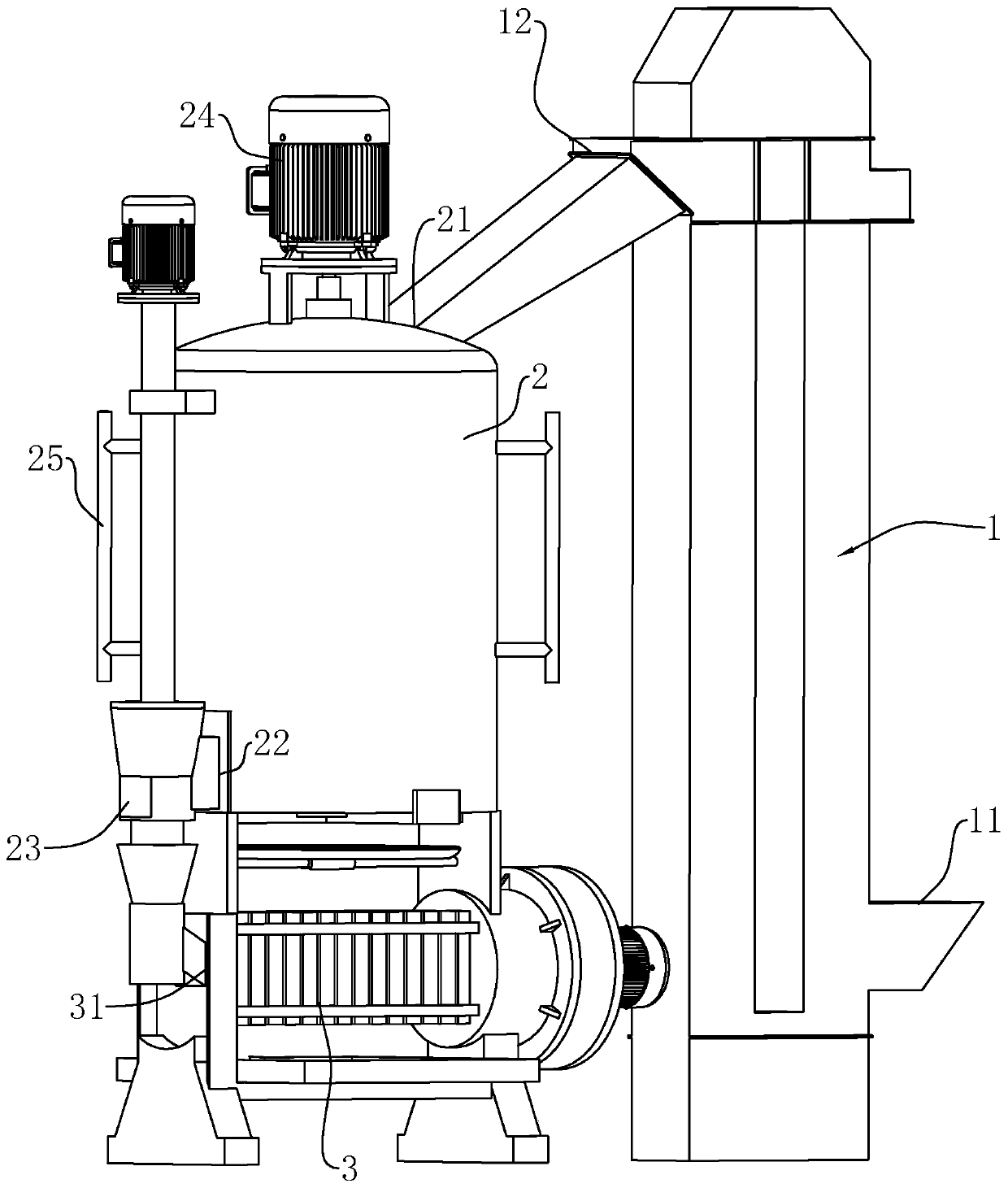
[0047] Such as figure 2 and 3 As shown, the side of the cooking tank 2 is provided with a hoist 74, the oil press 3 is located below the cooking tank 2, and the hoist 74, the cooking tank 2 and the oil press 3 are connected to each other.

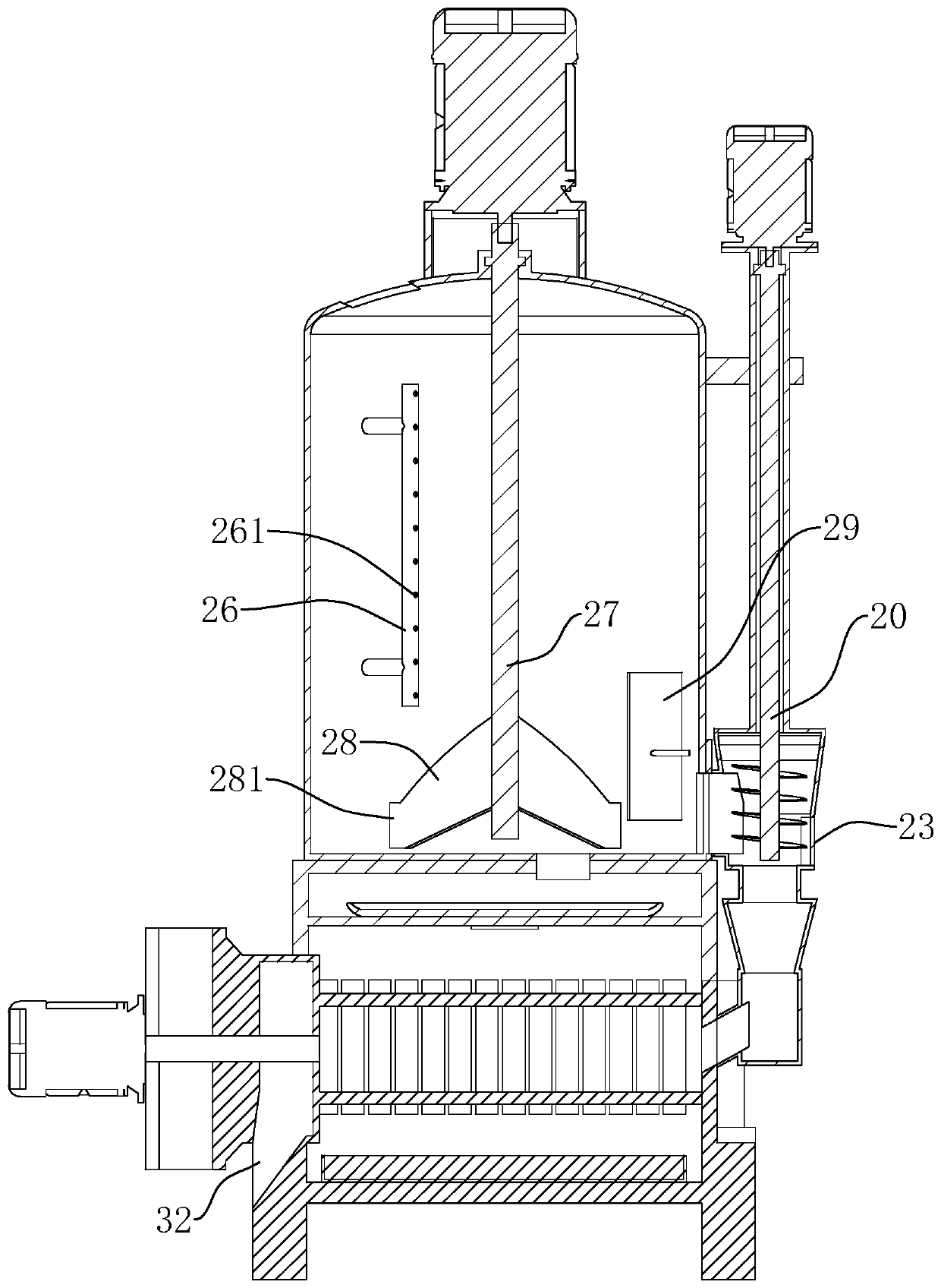
[0048] Elevator 74 includes feeding inlet 11 and feeding outlet 12; cooking tank 2 includes raw material inlet 21 and raw material outlet 22; feeding inlet 11 of elevator 74 is connected with raw material inlet 21 of cooking tank 2, and oil press 3 includes a third feed Port 31 and the third discharge port 32, the raw material outlet 22 of the cooking tank 2 and the third feed of the oil press 3 are connected.

[0049] A steam pipe 26 is provided on the inner side wall of the cooking tank 2 , and a plurality of ...

Embodiment 2

[0078] Such as Figure 16 As shown, the difference from Embodiment 1 is that the helical blade 542 is divided into two sections, the left blade 5421 and the right blade 5422, which rotate in opposite directions. One end of the left blade 5421 and one end of the right blade 5422 are close to each other and both are located at the feed outlet 1063 below.

[0079] When the rotating shaft 109 rotates, the left blade 5421 and the right blade 5422 push the material away to the left and right sides respectively.

Embodiment 3

[0081] Such as Figure 17 As shown, the difference from the second embodiment is that a push pedal blade 543 is arranged between the left blade 5421 and the right blade 5422, and the push pedal blade 543 is also fixedly connected to the rotating shaft 109, and the push pedal blade 543 is in the shape of a plate. The section can be arc-shaped, and the bending direction of the push plate blade 543 is opposite to the rotation direction of the rotating shaft 109 . At the same time, a plurality of push plate blades 543 can be arranged on the rotating shaft 109 , and the plurality of push plate blades 543 are evenly distributed along the circumference of the rotating shaft 109 .

[0082] Of course, the end of the left blade 5421 away from the feed outlet 1063 and the end of the right blade 5422 away from the feed outlet 1063 may also be respectively provided with push plate blades 543 .

[0083] When the rotating shaft 109 rotates, a part of the material can be directly pushed to t...


PUM


Abstract

The invention discloses a meat protein production line for feed. The technical scheme is characterized in that the meat protein production line includes a steaming and cooking pot, an oil press, a drying machine, a cooling machine, a grinder, a rotary sieve and a feeding hopper, wherein the steaming and cooking pot, the oil press, the drying machine, the cooling machine, the grinder, the rotary sieve and the discharge hopper are connected in sequence; the rotary sieve includes a first discharge hole from which the qualified feed is discharged, and a second discharge hole from which the large pellet feed is discharged, the first discharge hole is communicated with a feeding hole, and the purpose of using oil residues as raw materials for efficiently preparing meat protein for the feed is achieved.

Description

technical field [0001] The invention relates to the field of feed production, in particular to a meat protein production line for feed. Background technique [0002] As one of the main ingredients in the feed, meat protein is mainly used to increase the protein content of animals and improve the meat quality of animals. [0003] The existing meat protein production device can combine the patent with the notification number CN203424276U to cook fresh miscellaneous fish through a cooking machine, and then pass through a squeezer, a concentration mixer and a dryer to obtain high-quality fish protein powder for feed. But when the raw materials used are different, the technological process used also needs to be adjusted accordingly. When oil residue is used as raw material, the production technology of the prior art is not suitable. Contents of the invention [0004] The purpose of the present invention is to provide a meat protein production line for feed, which has the advan...

Claims


Application Information

Patent Timeline
Patent Type & Authority Patents(China)
IPC IPC(8): A23N17/00B07B1/28B07B1/42
Inventor 尹国军
Owner 北京中科昊盈生物技术有限公司
Why Eureka
Try Eureka