
High-speed stamping machine

A high-speed technology for stamping machines, applied in the field of stamping machines, can solve the problems of inconvenient use, low work efficiency, easy hand fatigue, etc., and achieve the effects of convenient use, improved work efficiency, and easy operation.

Pending Publication Date: 2017-07-21
广州市昊源通信设备有限公司
View PDF0 Cites 2 Cited by
  • Summary
  • Abstract
  • Description
  • Claims
  • Application Information

AI Technical Summary

Problems solved by technology

[0002] In daily life, many documents need to be stamped to be effective. In this way, people need to use stamps to stamp documents one by one in daily life. Especially, public affairs units need to stamp documents in batches. In daily life, stamping is generally done manually. In this way, when the stamping time is long, the hands are prone to fatigue, causing inconvenience in use, and at the same time, the stamping cannot be done continuously, resulting in low work efficiency. In addition, different departments in the existing office system basically have to manage a stamp. Therefore, the existing office The system needs to be able to replace a variety of seals, and the workload of stamping is very huge, and efficiency commissions are required to meet the requirements of efficient office and resource saving
Most of the existing automatic stamping machine mechanisms adopt the structure of vertical movement to achieve the purpose of stamping, and the existing closed stamping machines cannot be used for stamping documents of various sizes
In addition, the existing stamping machines generally do not have a stamp changing mechanism, and only realize a single, single stamping action, which cannot meet the needs of users. Therefore, we propose a high-speed stamping machine

Method used

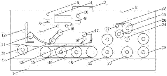
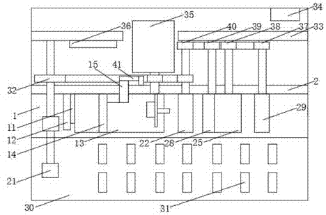

Image

  • High-speed stamping machine
  • High-speed stamping machine

Examples


Embodiment Construction

[0014] The following will clearly and completely describe the technical solutions in the embodiments of the present invention with reference to the accompanying drawings in the embodiments of the present invention. Obviously, the described embodiments are only some, not all, embodiments of the present invention. Based on the embodiments of the present invention, all other embodiments obtained by persons of ordinary skill in the art without making creative efforts belong to the protection scope of the present invention.

[0015] see Figure 1-2 , the present invention provides a technical solution: a high-speed stamping machine, including a base 1, a first support plate 2 is provided in the middle of the upper end of the base 1, and a hand strap 3 is provided in the middle of the upper end of the first support plate 2 In order to facilitate the taking of the stamping machine, the hand strap 3 is provided with a display screen 4 on the upper left side of the front side of the fi...


PUM


Abstract

The invention discloses a high-speed stamping machine. The machine comprises a base; a first supporting plate is arranged in the middle of the upper end of the base; a hand strap is arranged in the middle of the upper end of the first supporting plate; a display screen is arranged at the upper part of the left side of the front side of the first supporting plate; a reset button and an overload switch are arranged on the left side of the display screen; a motor indicating light and an overload indicating light are arranged at the lower end of the display screen; a displacement gear and a power switch are arranged on the right side of the display screen; a first fixing shaft is arranged at the upper part of the left side of the front side of the first supporting plate; and the left side of the first fixing shaft is connected with a baffle through a bolt. According to the high-speed stamping machine, the structure of a first pulley block and a speed-reducing baffle is arranged, can perform stamping full automatically and continuously and is easy to operate, so that the working efficiency can be greatly improved; and the structure of a first inking wheel and a second inking wheel is arranged, a lot of ink can be adsorbed and is free from leakage, and continuous working can be realized after one-time filling.

Description

technical field [0001] The invention relates to the technical field of stamping machines, in particular to a high-speed stamping machine. Background technique [0002] In daily life, many documents need to be stamped to be effective. In this way, people need to use stamps to stamp documents one by one in daily life. Especially, public affairs units need to stamp documents in batches. In daily life, stamping is generally done manually. In this way, when the stamping time is long, the hands are prone to fatigue, causing inconvenience in use, and at the same time, the stamping cannot be done continuously, resulting in low work efficiency. In addition, different departments in the existing office system basically have to manage a stamp. Therefore, the existing office The system needs to be able to replace a variety of seals, and the workload of stamping is very huge, and efficiency commissions are required to meet the requirements of efficient office work and resource saving. M...

Claims


Application Information

Patent Timeline
Patent Type & Authority Applications(China)
IPC IPC(8): B41K3/04B41K3/62B41K3/60B41K3/34
CPCB41K3/04B41K3/34B41K3/60B41K3/62Y02P70/10
Inventor 钱兴斌
Owner 广州市昊源通信设备有限公司
Learn More