Sucker rod pulling out and lifting device used for oil field operation

A lifting device and sucker rod technology, which is applied to drill pipes, drilling equipment, earth-moving drilling, etc., can solve the problems of small diameter of sucker rods and high labor intensity of employees, so as to reduce the number of liftings and improve the operation efficiency. , the effect of improving the degree of automation

Active Publication Date: 2017-07-21
大庆三环机械制造有限公司
View PDF10 Cites 2 Cited by
  • Summary
  • Abstract
  • Description
  • Claims
  • Application Information

AI Technical Summary

Problems solved by technology

However, in fact, because the diameter of the sucker rod is small and easy to bend, the existing oil pipe lifting and conveying device and the oil pipe up and down slide device cannot be applied to the sucker rod. Lifting the sucker rods requires a lot of labor intensity

Method used


Image

  • Sucker rod pulling out and lifting device used for oil field operation
  • Sucker rod pulling out and lifting device used for oil field operation
  • Sucker rod pulling out and lifting device used for oil field operation

Examples


Embodiment Construction

[0020] The present invention will be further described below in conjunction with accompanying drawing:

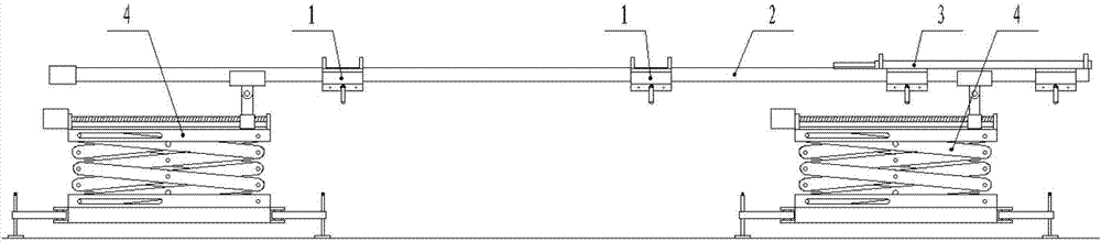
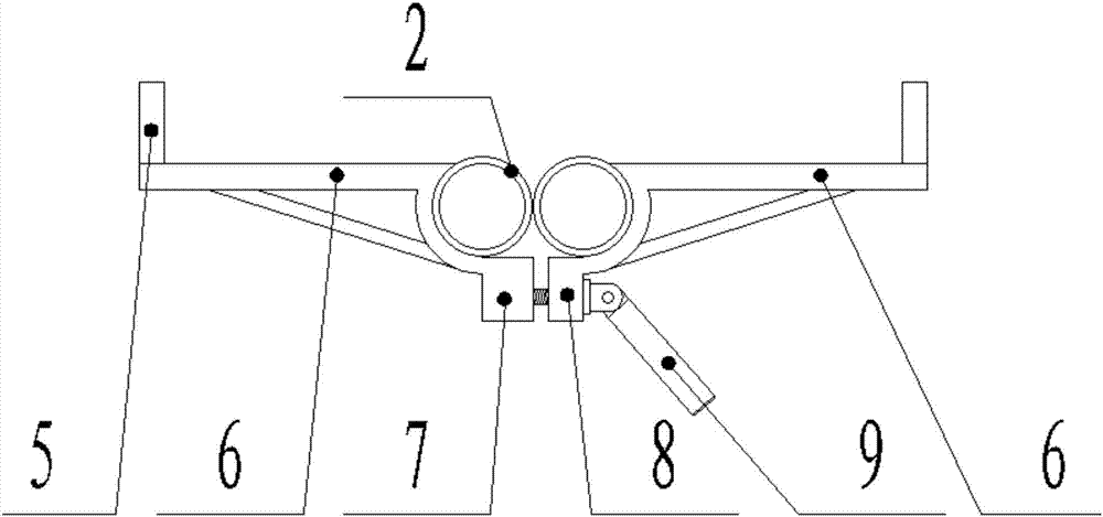
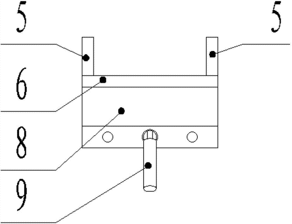
[0021] This embodiment includes a lifting conveying device 4 and a slideway 2, the slideway 2 is fixedly installed on the lifting device 4, and can be lifted and moved and axially moved under the drive of the lifting device 4, the slideway 2 is composed of two The oil pipes are arranged side by side and close together. The above is the basic structure of the automation device used for conveying oil pipes in the prior art, and since it is the prior art, it will not be repeated here.

[0022] The main innovation point of the present invention is that the present invention also includes a front support rod device 1 and a rear support rod device 3 , both of which are fixedly installed on the slideway 2 . When lifting and lowering the sucker rod, multiple sucker rods can be placed on the sucker rod bracket of the present invention at one time (the specific number of sucker rods...


PUM


Abstract

The invention belongs to the field of auxiliary devices of oil field well site operation and particularly relates to a sucker rod pulling out and lifting device used for oil field operation. The sucker rod pulling out and lifting device comprises a lifting conveying unit and a slide way. The slide way is fixedly formed in the lifting device and can make lifting movement and axial movement through driving of the lifting device. The slide way is formed by combining two oil pipes in a parallel and tightly-closed mode. The sucker rod pulling out and lifting device further comprise a front supporting rod unit and a rear supporting rod unit which are fixedly installed on the slide way, and when being pulled out, a plurality of sucker rods are placed on a sucker rod supporting frame of the sucker rod pulling out and lifting device at a time, and the sucker rods do not need to be lifted one by one, so that multiple times of lifting is changed into once; and by reducing the number of times of lifting, the purpose for improving operating efficiency of the sucker rods is achieved. According to the sucker rod pulling out and lifting device used for oil field operation, an existing oil pipe lifting conveying unit is applied in to the conveying process of the sucker rods, the automatic degree when the sucker rods are pulled out is improved, and labor intensity of a staff is relieved.

Description

technical field [0001] The invention belongs to the field of auxiliary devices for oilfield wellsite operations, in particular to a sucker rod lifting device for oilfield operations. Background technique [0002] With the continuous improvement of oilfield machinery automation, the oil pipe lifting and conveying device is widely used in minor maintenance operations, which significantly improves the operating efficiency when lifting and lowering oil pipes. When using the oil pipe lifting and conveying device, fix the oil pipe slideway (usually composed of two oil pipes side by side and closely combined) on the oil pipe lifting conveying device, and then place the oil pipe from the side of the oil pipe slideway through the oil pipe up and down slide device. On the oil pipe slideway, finally, by controlling the oil pipe lifting and conveying device, the oil pipe placed on the oil pipe slideway can be lifted or moved axially together with the oil pipe slideway, thereby realizing...

Claims


Application Information

Patent Timeline
Patent Type & Authority Applications(China)
IPC IPC(8): E21B19/14
CPCE21B19/14
Inventor 田国富周恒仓
Owner 大庆三环机械制造有限公司
Why Eureka
Try Eureka