
Positioning device of ultralarge excavator track pin shaft

A technology for positioning devices and excavators, applied to mechanical equipment, connecting components, etc., can solve the problems of high machining cost, difficult casting process, wear, etc., to avoid falling blocks or parts failure, avoid manufacturing shape and position errors, The effect of reducing casting risk

Active Publication Date: 2017-07-21
XUZHOU XCMG MINING MACHINERY CO LTD
View PDF7 Cites 0 Cited by
  • Summary
  • Abstract
  • Description
  • Claims
  • Application Information

AI Technical Summary

Problems solved by technology

[0003] The traditional pin positioning method is mostly to install only custom-made nuts on the track pad near the end of the pin shaft, or to reserve a boss with a specific shape on the track pad and machine it. The casting process is difficult and the machining cost is high. , during the working process, the pin shaft can rotate circumferentially and move axially, and the end touches the positioning nut, which will cause serious wear to the end of the pin shaft and the positioning nut, and the wear problem will be more serious after long-term use, and it is not loose The effect is not good, and the risk of the pin falling off and the complete machine losing its ability to move is high; in addition, the positioning device is mostly for one-time use, and when the connected track needs to be untied, the positioning device must be removed, which is time-consuming and laborious

Method used


Image

  • Positioning device of ultralarge excavator track pin shaft
  • Positioning device of ultralarge excavator track pin shaft
  • Positioning device of ultralarge excavator track pin shaft

Examples


Embodiment Construction

[0020] The present invention will be further described below in conjunction with the accompanying drawings. The following examples are only used to illustrate the technical solution of the present invention more clearly, but not to limit the protection scope of the present invention.

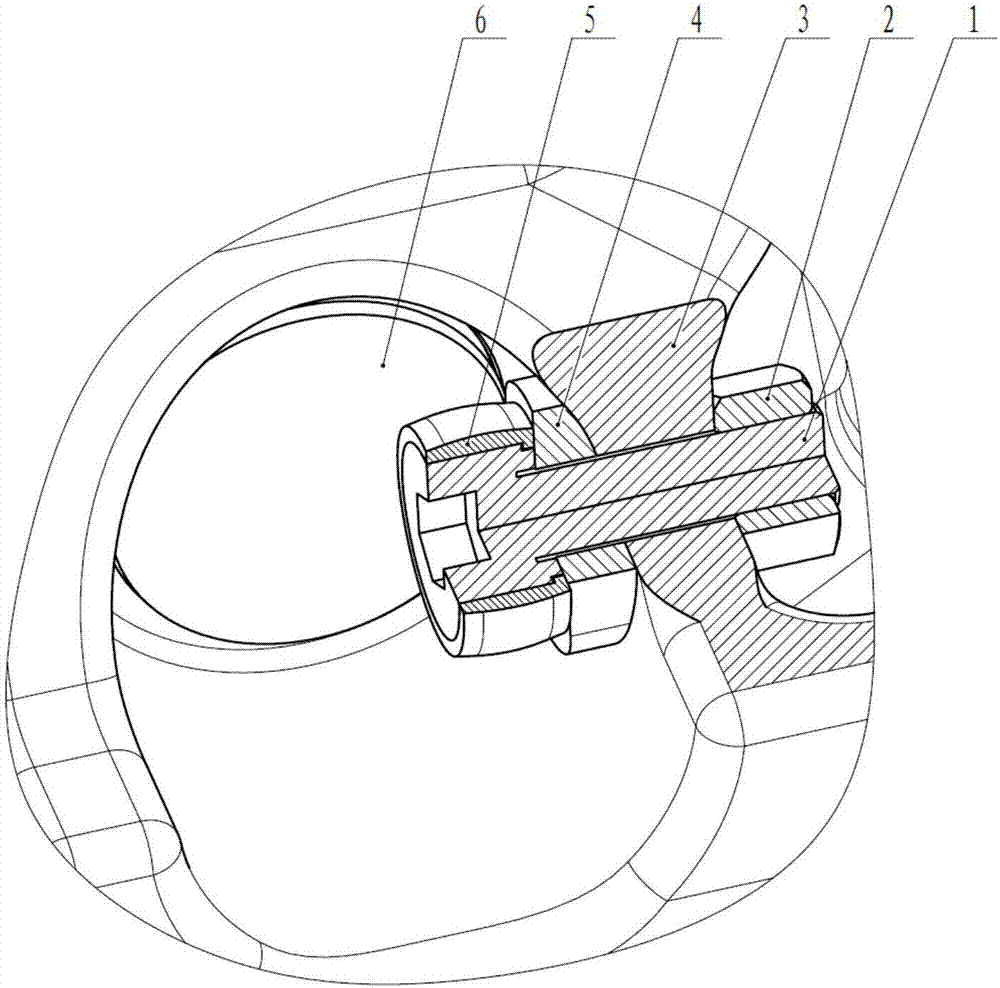
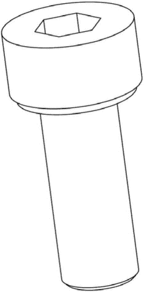
[0021] Such as figure 1 As shown, a positioning device for a super large excavator track pin is characterized in that it includes a track shoe 3, a pin shaft 6, a nut 2, a hexagon socket head cap screw 1, a spacer 4 and a drum sleeve 5. The device is located at the outer end of the pin shaft 6 and installed horizontally. After the two track shoes 3 are put together, use the pin shaft 6 to pass through the pin holes sequentially from the outside to the inside. Spacer 4, adjust the arc surface of the spacer 4 to match the arc surface of the track shoe 3 and tighten the nut 2, so as to realize the axial positioning of the pin shaft.

[0022] Preferably, the head of the hexagon socket head cap scr...


PUM


Abstract

The invention discloses a positioning device of an ultralarge excavator track pin shaft. The positioning device comprises a pin shaft for connecting with a track plate, and a positioning device for positioning the pin shaft. The positioning device is characterized in that the positioning device is horizontally arranged at the outer side end part of the pin shaft; the positioning device comprises a transition piece, a limiting piece, and a fixed piece for connecting the limiting piece with the transition piece; a gap is formed between the limiting piece and the end surface of the pin shaft; the transition piece is provided with an arc surface matched with a track plate arc surface for preventing arrangement of a complicated mounting boss on a track plate and machining; and the fixed piece penetrates through the limiting piece and the transition piece for fixation in sequence. The positioning device has the following advantages: the positioning device uses a spacing sleeve with an arc surface as the transition piece for preventing arrangement of the complicated mounting boss on the track plate and machining to reduce the casting risk; the positioning device uses a drum-shaped sleeve for axially positioning the track pin shaft to prevent wear of such parts as the pin shaft; and the positioning device is simple in structure, convenient to disassemble and high in reliability.

Description

technical field [0001] The invention relates to a positioning device for a track pin shaft of an ultra-large excavator, and belongs to the technical field of walking devices for heavy engineering machinery tracks. Background technique [0002] The walking system of super large excavators generally consists of crawler tracks, driving wheels, supporting wheels, drag chain wheels and guide wheels. Among them, the crawler is the core component, and it is the carrier that converts the driving force of the walking motor into the walking power of the whole machine. The track shoes of ultra-large excavators are generally integrally cast, and the pin shafts are used to pass through the pin holes for connection. When walking, the track shoes and pin shafts are very stressed, and will deform over time. Therefore, the reliability of the positioning of the crawler pin shaft determines the reliability of the crawler traveling device to a large extent. [0003] The traditional pin positi...

Claims


Application Information

Patent Timeline
Patent Type & Authority Applications(China)
IPC IPC(8): F16B21/10
CPCF16B21/10
Inventor 渠立红杨裕丰丁跃进付相华李乃柱焦青
Owner XUZHOU XCMG MINING MACHINERY CO LTD
Learn More