Multi-link rotation structure

A rotating structure and multi-link technology, applied in the direction of transmission, belt/chain/gear, mechanical equipment, etc., can solve the problems of low energy loss and no further research, and achieve simple overall structure, low cost and easy assembly easy effect

Active Publication Date: 2017-07-21
黄明仕
View PDF4 Cites 0 Cited by
  • Summary
  • Abstract
  • Description
  • Claims
  • Application Information

AI Technical Summary

Problems solved by technology

[0003] However, such known connection or transmission mechanism is connected between a driving device and a driven device, only as a medium for transmitting power, and its configuration generally only considers the installation between the driving device and the driven device. Space, configuration relationship, and movement degree (such as speed, or stroke, etc.) factors, as for how to use these mechanisms to form a system with the lowest energy loss, the most continuous movement, and the ability to output energy efficiently, there is no further study.

Method used


Image

  • Multi-link rotation structure
  • Multi-link rotation structure
  • Multi-link rotation structure

Examples


Embodiment Construction

[0024] The following examples illustrate possible implementations of the present invention, but are not intended to limit the protection scope of the present invention.

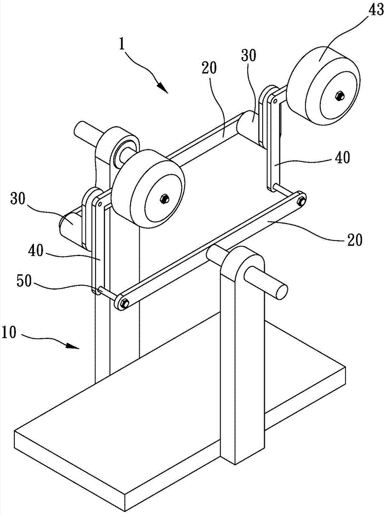
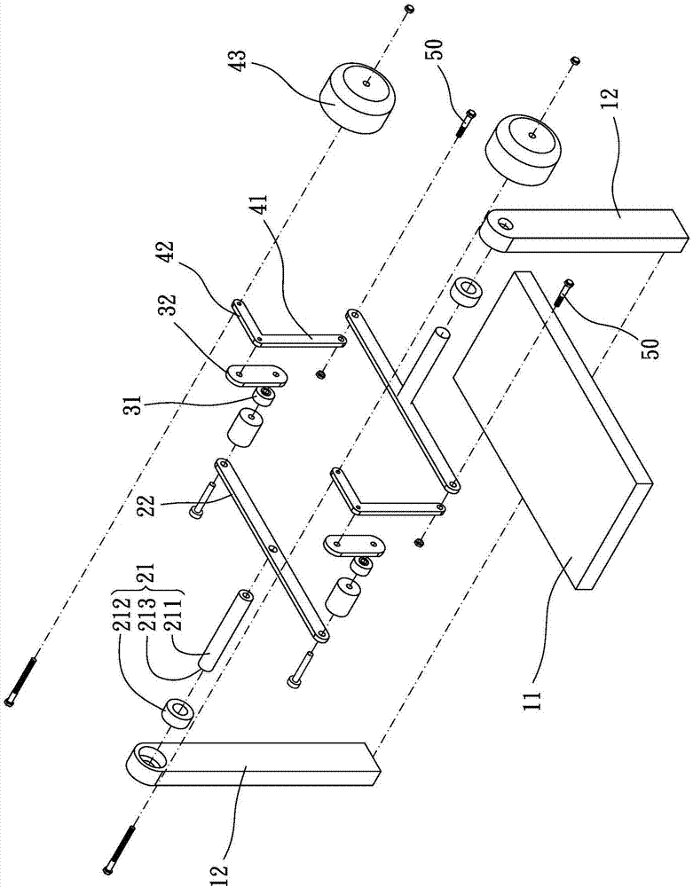
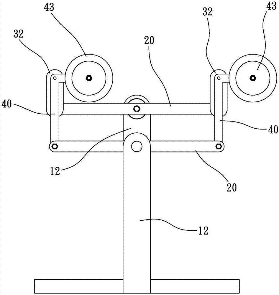
[0025] Please refer to figure 1 and image 3 , which shows a preferred embodiment of the present invention, the multi-link rotating structure 1 of the present invention includes a frame 10 , two arm groups 20 , at least two unidirectional rotating devices 30 and at least two link groups 40 .

[0026] Each arm set 20 includes a pivot 21 pivotally connected to the frame 10 and at least two arms 22 connected to the pivot 21 and extending in different directions (preferably, the at least two arms 22 are directly connected to the pivot by the pivot start and extend in different directions, and can also be connected to the pivot portion 21 indirectly (for example, turning or through other connecting components), the pivot portion 21 of the two arm groups 20 is not coaxially arranged. The at least two one-way rota...


PUM


Abstract

A multi-link rotation structure is provided, including: a base; two arm assemblies, each of the two arm assemblies including a pivot portion pivoted to the base and at least two arms connected with the pivot portion and extending away from each other, the pivot portions of the two arm assemblies being non-coaxial; at least two unidirectional rotation devices, respectively axially pivoted to the arms of one of the two arm assemblies, rotatable in a same direction; at least two linkage assemblies, each of the at least two linkage assemblies pivoted to the arms of the other of the two arm assemblies and pivoted to one of the at least two unidirectional rotation devices.

Description

technical field [0001] The invention relates to a multi-link rotating structure. Background technique [0002] Many devices or machinery will be equipped with connection and transmission mechanisms, such as gears, chains or multi-links, etc., through which the energy of such as engines, motors, fans or similar devices is transmitted to the outside world for applications, such as driving machines Running, driving the runner to rotate or driving the generator set to generate electricity, etc., has extremely diverse functions and is widely used, and it is a very important mechanism today. [0003] However, such known connection or transmission mechanism is connected between a driving device and a driven device, only as a medium for transmitting power, and its configuration generally only considers the installation between the driving device and the driven device. Space, configuration relationship, and movement degree (such as speed, or stroke, etc.) factors, as to how to use t...

Claims


Application Information

Patent Timeline
Patent Type & Authority Applications(China)
IPC IPC(8): F16H21/16
CPCF16H21/12F16H29/12F16H21/16
Inventor 黄明仕
Owner 黄明仕
Why Eureka
Try Eureka