High-rigidity composite pipeline and manufacturing method thereof

A composite material and high-stiffness technology, applied in the direction of rigid pipes, pipeline protection, chemical instruments and methods, etc., can solve problems such as construction difficulties, damage and damage, easy deformation, etc., to improve the section moment of inertia of the pipe wall, improve the rigidity of the pipe, The effect of high reliability

Inactive Publication Date: 2017-07-21
TIANJIN POLYTECHNIC UNIV
View PDF8 Cites 10 Cited by
  • Summary
  • Abstract
  • Description
  • Claims
  • Application Information

AI Technical Summary

Problems solved by technology

However, the disadvantage of low rigidity of resin-based pipelines makes them easy to deform and even cause damage under poor geological conditions or poor backfill construction.
If the high-rigidity resin-based pipe is made according to the existing structure and manufacturing process, the cost will inevitably increase a lot, and the weight will also increase a lot, which is not conducive to its popularization and application
As a kind of resin-based composite pipe, the FRP sand-filled pipe adopts the sandwich structure of resin-quartz sand, which reduces the cost to a certain extent. Although the cost is reduced to a certain extent, it is difficult to construct, especially easy to deform during the construction process.

Method used


Image

  • High-rigidity composite pipeline and manufacturing method thereof

Examples


Embodiment Construction

[0022] The following examples further illustrate the technical solutions of the present invention, but are not intended to limit the protection scope of the present invention.

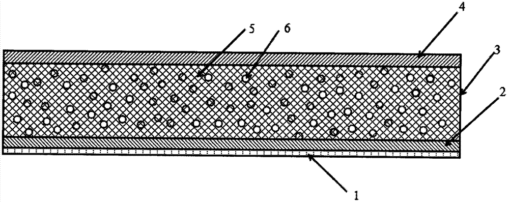
[0023] Referring to the accompanying drawings, a high-rigidity composite material pipeline of the present invention includes an inner lining layer 1, a structural layer 2, a sandwich structure 3, and a protective layer 4 from the inside to the outside. Among them, the inner lining layer, structural layer, and protective layer are all made of resin-based composite materials by winding technology, and the sandwich structure 3 is covered with a resin-impregnated warp-knitted spacer fabric 5 on the surface of the structural layer, and the resin is cured to form a certain thickness. Hollow sandwich structure; the hollow sandwich structure can also be filled with lightweight foam plastics 6 to form a solid sandwich structure.

[0024] The sandwich structure 3 is coated on the surface of the structural layer ...


PUM

PropertyMeasurementUnit
thicknessaaaaaaaaaa
thicknessaaaaaaaaaa
thicknessaaaaaaaaaa

Abstract

Disclosed are a high-rigidity composite pipeline and a manufacturing method thereof. A lining layer, a structure layer, an interlayer structure and a protective layer are arranged sequentially from inside to outside. The lining layer, the structure layer and the protective layer are all prepared from fibers or fabric-reinforced resin-based composites through a winding process. The surface of the structure layer is coated with the interlayer structure through warp-knitted spacer fabrics soaked with resin, and the hollow interlayer structure is formed through resin curing, or the hollow interlayer structure is filled with light foamed plastics to form a solid interlayer structure. According to the high-rigidity composite pipeline and the manufacturing method thereof, the hollow interlayer structure or the interlayer structure filled with the light foamed plastics is adopted, thus the weight of the pipeline is reduced substantially, and small weight is achieved. Meanwhile, due to the fact that the interlayer structure is adopted, larger pipe wall thickness can be achieved with less materials, the inertia moment of the pipe wall section is improved greatly, the rigidity of the pipeline is improved, and thus high rigidity and low cost are achieved.

Description

technical field [0001] The invention relates to a composite material pipeline for transporting various media and a manufacturing method thereof, in particular to a high-rigidity composite material pipeline. Background technique [0002] At present, there are many types of pipes in the water supply and drainage industry, such as concrete pipes, steel pipes, resin-based composite pipes, etc., which are more common. Each type of pipe has its advantages and disadvantages. For example, steel pipes have high strength and rigidity, but are easy to rust; concrete pipes have high rigidity and low price, but poor hydraulic performance and heavy weight; resin-based composite pipes mainly refer to composite material pipes made of resin as the matrix after reinforcement, such as fiber reinforced pipes. Plastic pipe with excellent corrosion resistance and hydraulic properties, but with low stiffness. In terms of comprehensive comparison, resin-based composite pipe, as a kind of composite...

Claims


Application Information

Patent Timeline
Patent Type & Authority Applications(China)
IPC IPC(8): F16L9/14F16L57/02B32B1/08B32B27/04B32B27/12B32B3/08B32B33/00
CPCF16L9/14B32B1/08B32B3/08B32B27/12B32B33/00B32B2260/021B32B2260/046B32B2307/50B32B2307/718F16L57/02
Inventor 吴晓青魏俊富肖沅谕
Owner TIANJIN POLYTECHNIC UNIV
Why Eureka
Try Eureka