
Multi-stage loading testing device for simulating excavation of rock mass in different dip angles

A loading test device and loading device technology, applied in the direction of applying stable tension/pressure to test the strength of materials, etc., can solve the problems of affecting the accuracy of test results, excessive deviation of test results, cumbersome component pouring, etc., and achieve easy operation and The effect of loading, convenient test and accurate test results

Inactive Publication Date: 2017-07-21
HOHAI UNIV
View PDF5 Cites 3 Cited by
  • Summary
  • Abstract
  • Description
  • Claims
  • Application Information

AI Technical Summary

Problems solved by technology

However, during the simulation test, due to the size limitation of the test frame, the pouring of the components was too cumbersome, and the lateral loading position was fixed, which was basically single-point loading, resulting in excessive deviation of the test results
In addition, the existing test devices are basically under one-sided pressure, which is quite different from the field conditions, which also affects the accuracy of the test results.

Method used


Image

  • Multi-stage loading testing device for simulating excavation of rock mass in different dip angles
  • Multi-stage loading testing device for simulating excavation of rock mass in different dip angles
  • Multi-stage loading testing device for simulating excavation of rock mass in different dip angles

Examples


Embodiment 1

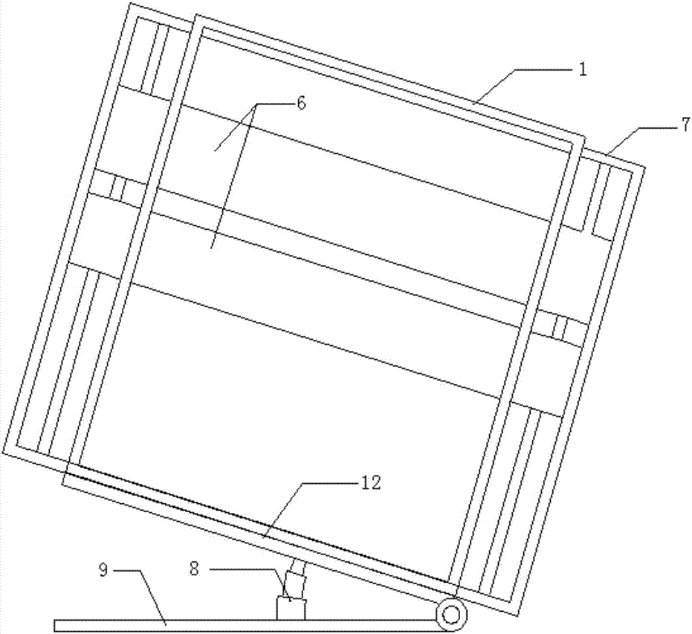
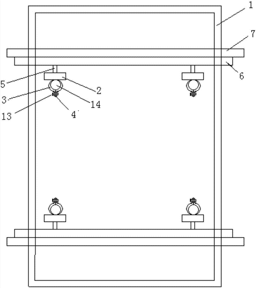
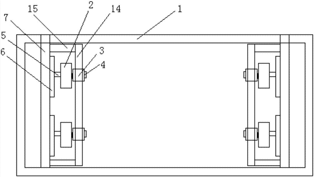
[0024] Such as Figure 1-5 As shown, a multi-stage loading test device for simulating the excavation of rock masses with different inclinations includes an outer frame and a multi-stage loading device. The outer frame includes a fixed frame, a tiltable steel plate, a hydraulic lifting column and a fixed bottom plate. It is located at the bottom of the fixed frame, the top of the hydraulic lifting column is connected to the bottom surface of the tiltable steel plate, and the fixed end of the hydraulic lifting column is connected to the fixed bottom plate; the multi-stage loading device is installed on the fixed frame, and the multi-stage loading device includes the inner frame, steel plate, reset device, electromagnetic loading device and connecting fasteners. The inner frame includes an inner frame body, a connecting pipe and two vertical steel pipes. The two vertical steel pipes are respectively arranged outside the two ends of the inner frame body. The upper and lower ends o...

Embodiment 2

[0028] It is basically the same as Embodiment 1, except that there are more than two multi-stage loading devices arranged in parallel on the fixed frame.


PUM


Abstract

The invention discloses a multi-stage loading testing device for simulating excavation of a rock mass in different dip angles. The multi-stage loading testing device comprises an outer frame and a multi-stage loading device, wherein the outer frame comprises a fixing frame, an inclined steel plate, a hydraulic lifting column and a fixing bottom plate; the multi-stage loading device is arranged on the fixing frame; the multi-stage loading device comprises an inner frame, a steel plate, return devices, electromagnetic loading devices and connecting buckles; the inner frame comprises an inner frame body, a connecting tube and two vertical steel tubes; the upper ends and the lower ends of the two vertical steel tubes are respectively connected with the upper end and the lower end of the inner frame; the inner frame is in sliding connection with two sides of the fixing frame; the steel plate is fixedly connected with the frame; one sides of two electromagetnic loading devices are connected with the two vertical steel tubes through the connecting buckles respectively; the other sides of the two electromagetnic loading devices are connected with the steel plate through the return devices. The multi-stage loading testing device is simple in principle, easy to operate and load, convenient in testing, relatively approximate to actual excavation situations of sites, and relatively accurate in testing result.

Description

technical field [0001] The patent of the invention relates to a multi-stage loading test device for simulating the excavation of rock masses with different dip angles, and belongs to the technical field of teaching and test auxiliary equipment. Background technique [0002] After the rock mass is excavated, the stability research under the action of external force has always been the focus of scientific research and engineering circles. In particular, the vibration generated during the blasting construction process will inevitably have a great impact on the surrounding buildings. For this reason, there are more and more experimental devices for blasting excavation in the laboratory. However, during the simulation test, due to the limitation of the size of the test frame, the pouring of the components was too cumbersome, and the lateral loading position was fixed, which was basically a single point loading, resulting in excessive deviation of the test results. In addition, t...

Claims


Application Information

Patent Timeline
IPC IPC(8): G01N3/08
CPCG01N3/08
Inventor 单鹏刘军刘明清刘光昆
Owner HOHAI UNIV
Learn More