Gauge detection ranging method and system based on camera and controllable stroboscopic light source

A distance measurement method and strobe technology, which are applied to TV system components, measuring devices, color TV components, etc., can solve problems such as difficult matching, huge amount of data calculation, and large amount of data, and achieve the goal of overcoming ambient light. The effect of large influence, high measurement accuracy and high speed measurement accuracy

Active Publication Date: 2017-07-21
CENT SOUTH UNIV
View PDF2 Cites 9 Cited by
  • Summary
  • Abstract
  • Description
  • Claims
  • Application Information

AI Technical Summary

Problems solved by technology

The general stereo vision detection technology based on point matching of the same name has complex algorithms, difficult matching, limited frame rate and huge amount of data calculation. It can get better results in the case of low speed and fixed detection objects, but it is difficult to meet the requirements of high speed and changing environment.
The triangular ranging limit detection method has the advantages of higher detection accuracy, denser circumferential sampling points and higher longitudinal sampling frequency, but the limit detection speed is faster, there are more vertical and horizontal measuring points, and the amount of data is large. The switching speed of each unit on the board cannot meet the requirements, making it difficult to achieve high-speed online detection

Method used


Image

  • Gauge detection ranging method and system based on camera and controllable stroboscopic light source
  • Gauge detection ranging method and system based on camera and controllable stroboscopic light source
  • Gauge detection ranging method and system based on camera and controllable stroboscopic light source

Examples


Embodiment

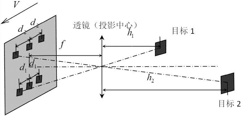
[0050] The present invention is an embodiment of a limit detection and distance measurement method based on a camera and a controllable strobe light source. The limit detection and distance measurement method is mainly suitable for high-speed online detection of railway boundaries, and provides object distance data for limit detection. The ranging method mainly includes the following steps:

[0051] First, under the state of train running, adjust the frame rate of the CMOS area array camera and the flash frequency of the controllable strobe light source, so that the controllable strobe light source performs multiple stroboscopic flashes in the same frame of the CMOS area array camera exposure period, and the frame The train movement corresponding to the time length is regarded as a constant speed, so that the measured object smaller than one-third of the field of view of the CMOS area array camera is periodically imaged in the same frame image of the CMOS area array camera.

...


PUM

PropertyMeasurementUnit
widthaaaaaaaaaa

Abstract

The invention discloses a gauge detection ranging method and system based on camera and controllable stroboscopic light source; when a train runs, frame frequency of a CMOS (complementary metal oxide semiconductor) camera and flashing frequency of a stroboscopic light source are adjusted so that the stroboscopic light source strobes many times within one frame of the exposure period of the CMOS camera, and a detection subject smaller than one-third of a visual field of the CMOS camera is periodically imaged within the same frame of the CMOS camera; the periodic image is subjected to Fourier transform, amplitude at specific frequency in an amplitude spectrum curve is maximum, a frequency corresponding to the maximum value is the number of pixels between repeated images of the detection subject within the strobing period, and a distance between the repeated images is acquired by multiplying the number of pixels between the repeated images of the detection subject within the stroking period by a length of each pixel of the camera; a distance to the detection subject is calculated according to the imaging principle of camera, and the method has high measuring precision and accuracy and is suitable for high-speed online detection of a railway.

Description

technical field [0001] The invention relates to the technical field of railway limit detection, in particular to a limit detection and ranging method and system based on a CMOS area array camera and a controllable frequency light source. Background technique [0002] Railway limit detection has always been highly valued by relevant railway departments, and it plays a vital role in improving railway transportation safety and transportation efficiency. At present, the test methods of limit detection mainly include contact limit detection and non-contact limit detection. [0003] In the early days of limit detection, the limit detection and ranging systems at home and abroad generally adopted the contact type, mainly including the mechanical tentacle type and the detection frame type. These two methods are to install a frame on the detection car, and during operation, the limit detection is realized by recording the contact between the frame and the surrounding objects. The de...

Claims


Application Information

Patent Timeline
Patent Type & Authority Applications(China)
IPC IPC(8): G01N21/01G01N21/84H04N5/232H04N5/235H04N5/247
CPCG01N21/01G01N21/84G01N2201/102H04N23/951H04N23/70H04N23/90
Inventor 鲁寨军梁习锋李鹏刘应龙
Owner CENT SOUTH UNIV
Why Eureka
Try Eureka